Table of Contents
Advertisement
Quick Links
Advertisement
Table of Contents

Related Manuals for Sim-Lab XP-1

Summary of Contents for Sim-Lab XP-1
- Page 1 INSTRUCTION MANUAL XP-1 PEDALS VERSION 1.0 Last updated: 11-09-2023...
-
Page 2: Before You Start
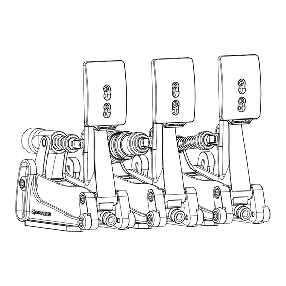
Thank you for your purchase. In this manual we will provide you with the means to get started using your new pedals! Introducing the Sim-Lab XP-1 200KG Loadcell Pedal Set! Simulate any pedal of any car with the most complete sim-racing pedal set available. Carefully crafted to satisfy the needs of serious sim racing enthusiasts, this top-notch and fully customizable pedal set is designed to take your on-track performance to new heights. -
Page 3: Installation
Installation Depending on your setup, the pedals can be mounted directly to both profile (P1-X) or pedal decks (like the GT1-EVO). Also the latest universal baseplate is also compatible with these new pedals so no matter which setup you own, there are ways to mount this pedal set. - Page 4 Pedal deck and baseplate Due to the 6mm slots, you can use almost every slot found on these products and it all comes down to personal preference. For baseplates, there still more than enough of possibilities. The obvious difference here is the lack of slot-nuts, and the inclusion of some additional washers to help protect your baseplate.
- Page 5 Configuration Pedal Base We tried to re-use as many parts throughout the pedals as possible. This means the configuration and adjustments are virtually the same for all three pedals. The angle of the pedal arm in relation to your cockpit can be changed by adjusting the pedal base.
- Page 6 Pedal Face One of the more simple adjustments is the ability to change the position and angle of the pedal face. Loosen the two bolts (F) holding the pedal face and you can adjust the position of the pedal face to your preference. As mentioned, it is also possible to change the angle of the pedal face.
- Page 7 Prepare for changing parts To get acces to the parts we can change, first we must temporarily remove the spring bolt (S), which keeps the clevis fork attached to the pedal arm. In this example we are using the throttle pedal. Release any tension from the spring by loosening any adjustment knob(s) before trying to remove the spring bolt.
- Page 8 Throttle configuration This pedal is easy to setup, be it stock or after you have changed the springs. There are two main options basically. The throttle spring can be adjusted to be more stiff or soft. Unlock the blue knobs and tighten (clockwise) the adjustment knob (A) for a stiffer throttle feel.
- Page 9 Adjusting spring force isn’t only possible by using the adjustment knobs. Using the lower of the three adjustment points on the pedal arm gives you a slightly softer (S) pedal pressure for example. The higher of the three a slightly firmer (F). Note: by the nature of the position of the clevis fork so low on the pedal arm, travel might be mechanically limited.
- Page 10 Brake configuration We will focus just on changing parts in this chapter. After you have followed the steps on page 7, you can now remove the clevis fork and shaft. This makes it very easy to change around parts to suit your preference. Keep in mind, all parts connected to the shaft are loose fitting.
- Page 11 In case you do not want any preload, we included a preload buffer(BOM) to replace the spring with. This is basically a spacer which replaces the spring. As a matter of fact, when you are going to install the preload buffer and do not want any preload all, remove the spring entirely.
-
Page 12: Control Box
All pedals are plugged into the control box the same way. All inputs are labeled, for reference, here is top-down drawing with the same information as found on the box. XP-1 PEDALS CONTROL BOX Every pedal uses the same connector, so you don’t have to worry about mixing up... - Page 13 First we need to activate the product, this is done on the ‘Settings’ (1) page. Tick the ‘ A ctivate’ tickbox next to ‘XP-1 Pedals’ (2) and its icon (3) should appear on the left side of the screen. Selecting the icon (3) will take us to its device pages.
- Page 14 Device page The device page for the pedals allow you to calibrate (1), adjust the input curves (2) and adjust deadzones (3). We will focus on the middle colum in this example, as their functionality is identical: Calibration - Press ‘Calibrate’ (1) for the device to enter calibration mode. - Press the pedal to the maximum travel or force, press ‘Finish calibration’...
-
Page 15: Maintenance
Maintenance Although the pedal set has bronze bushings and teflon parts, we do recommend to take care of your pedal set. Every now and then some cleaning and oiling will benefit performance and condition of your pedal set. As for lubrication ( ), we generally recommend WD-40 Specialist White Lithium Grease to lubricate moving parts. -
Page 16: Bill Of Materials
If you still have some questions regarding assembly of this product or about the manual itself, please refer to our support department. They can be reached at: support@sim-lab.eu Alternatively, we now have Discord servers where you can hang out or ask for help.
Need help?
Do you have a question about the XP-1 and is the answer not in the manual?
Questions and answers