Table of Contents
Advertisement
Quick Links
Advertisement
Table of Contents

Summary of Contents for Climer ECOHEAT TD EH200BT50-TD
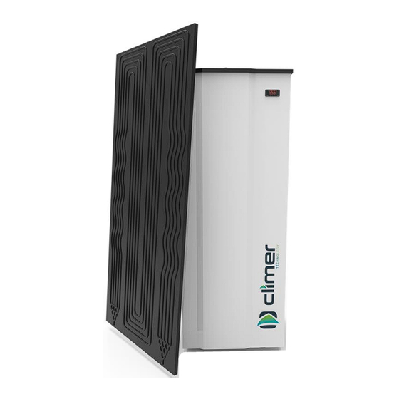
- Page 1 INSTALLATION AND USER MANUAL ECOHEAT TD EH200BT50-TD...
- Page 2 INSTALLATION AND USER MANUAL ECOHEAT TD V0REV1EN0423...
-
Page 3: Table Of Contents
INSTALLATION AND USER MANUAL ECOHEAT TD INTRODUCTION ......................1 GENERAL INDICATIONS ....................1 TECHNICAL INFORMATION .................... 3 INSTALLATION STEPS ....................6 THERMODYNAMIC PANEL PLACING ................7 ECOHEAT PLACING ...................... 10 CONNECTION BETWEEN ECOHEAT TD AND PANEL ..........10 HYDRAULIC CONNECTION ..................12 ELECTRICAL CONNECTION .................. -
Page 4: Introduction
It is necessary to carefully read this manual before making any handling to avoid problems arising from the misuse of the product. The company CLIMER TECHNOLOGY reserves the right to modify the information included in this document at any time without prior notice. - Page 5 INSTALLATION AND USER MANUAL ECOHEAT TD 2.3. Package contents The ECOHEAT system comprises the following components: - ECOHEAT TD unit - Thermodynamic panel - Anchoring elements - Silent-Blocks - User Manual 2.4. Indications about transport and unpacking the unit The unit is supplied packed into a wooden pallet properly secured to prevent damage during transport.
-
Page 6: Technical Information
INSTALLATION AND USER MANUAL ECOHEAT TD 3. TECHNICAL INFORMATION 3.1. Operating principle V0REV1EN0423... - Page 7 INSTALLATION AND USER MANUAL ECOHEAT TD 3.2. Dimension drawings It is possible to remove the side and front casing access easily to any part of the system. Connections and dimensions Hot water outlet, 3/4“ Serial buffer connection: Cap – Available for use, 1’’ Parallel buffer connection: Impulsion from outdoor unit, 1”...
- Page 8 INSTALLATION AND USER MANUAL ECOHEAT TD 3.3. Technical data Model EH200BT50TD DHW tank Capacity, L Maximum operating pressure, bar Buffer Buffer, L Maximum operating pressure, bar Heat pump data Energy Efficiency Class Load profile Heating capacity range, W 1430 – 2560 Input power range, W 450 –...
-
Page 9: Installation Steps
INSTALLATION AND USER MANUAL ECOHEAT TD Thermodynamic panel dimensions: 4. INSTALLATION STEPS Before starting the installation, check the availability of all the necessary components and tools: - High and low pressure manometers - Vacuum pump - Scales - Nitrogen bottle - Refrigerant quality copper pipe - Pipe-cutter - Tube bender... -
Page 10: Thermodynamic Panel Placing
INSTALLATION AND USER MANUAL ECOHEAT TD Once it has been checked that it is available all the necessary components and tools, the installer should follow the next steps: 1. Placing and anchoring panels 2. Joining and welding the refrigerant pipes 3. - Page 11 INSTALLATION AND USER MANUAL ECOHEAT TD - Distance to the equipment: The maximum distance allowed from the panels to the equipment is 15 meters (sum of the distances L1 + L2 + L3 + L4 in the following figure). When the panel is installed in vertical If the panel is installed at position, always the inlet and outlet horizontal position, refrigerant...
- Page 12 INSTALLATION AND USER MANUAL ECOHEAT TD 5.2. Anchoring panel Beside the panel, it is supplied a bag with anchoring elements that contains the following pieces: Ref. Qty. Panel Aluminium support (L shape) Screw M5 Washer Nut M5 Sheet metal screw Block M6 Anchor the panels using the lateral and front holes to the suitable surface.
-
Page 13: Ecoheat Placing
INSTALLATION AND USER MANUAL ECOHEAT TD 6. ECOHEAT PLACING The place where the system will be installed should allow an easy access in order to make maintenance work or inspection. Air outlet of ECOHEAT is around 5-10 degrees below inlet temperature, so in case that the exhaust air would not be ducted, the room temperature will be considerably reduced. - Page 14 INSTALLATION AND USER MANUAL ECOHEAT TD IMPORTANT (Only when welding is needed): It is recommended to weld pipelines by oxyacetylene welding. Welding is a critical step in the installation and to do it well ensures that the system will run properly along its useful life. Only expert staff should make this step by using proper tools and high-quality materials.
-
Page 15: Hydraulic Connection
INSTALLATION AND USER MANUAL ECOHEAT TD 8. HYDRAULIC CONNECTION The hydraulic connections are shown in the following scheme: The installer must install the following components of the hydraulic circuit: 1. Cold water inlet 10. DHW 2. Ball valve 11. Heating-cooling outlet 3. -
Page 16: Electrical Connection
INSTALLATION AND USER MANUAL ECOHEAT TD 9. ELECTRICAL CONNECTION The power supply of the system is 230 V/1/50 Hz. PV: Photovoltaic connection LPS: Low pressure switch HPS: High pressure switch NTC1: Water temperature probe NTC2: Not used D: Display VS: Not used R: Electrical heater K: Compressor F: Not used... -
Page 17: Comissioning. Controller
INSTALLATION AND USER MANUAL ECOHEAT TD 10. COMISSIONING. CONTROLLER 10.1. User interface description Symbol Meaning when it lights Compressor switched on Not used Not used Alarm active Compressor working hours exceeded Unit in ºC Unit in ºF Electric heater switched on Stand by V0REV1EN0423... - Page 18 INSTALLATION AND USER MANUAL ECOHEAT TD 10.2. Switching on After full installation of the water heater (power and water pipes connected) and after the water heater tank is full of water, power can be turn ON. 1. After filling the tank of water, connect the mains plug to the mains supply.
- Page 19 INSTALLATION AND USER MANUAL ECOHEAT TD 10.4. Unlocking the keypad When 30 have elapsed without the keys being pressed, the display will show the ‘’ LOC’’ label and the keypad will lock automatically. Touch any key until the screen shows UnL, to unlock the keypad.
- Page 20 INSTALLATION AND USER MANUAL ECOHEAT TD 10.6. Changing operating mode To change the operating mode, touch the key for 4 seconds. The screen will show blinking the selectable operating modes. Use the keys to select the operating mode. Touch to confirm or cancel.
- Page 21 INSTALLATION AND USER MANUAL ECOHEAT TD 10.7. ECO Mode ECO mode: Maximum savings. The system heats water only by heat pump technology. This is the factory default mode. Setting the ECO temperature setpoint The water temperature set point in ECO mode can be changed with the SP1 parameter. Touch key and select SP1.
- Page 22 INSTALLATION AND USER MANUAL ECOHEAT TD 10.8. AUTO Mode It maintains a steady temperature by the heat pump and only use the electrical heater if the temperature falls drastically. Setting the AUTO temperature setpoint The water temperature set point in AUTO mode can be changed with the SP2 parameter. Touch key and select SP2.
- Page 23 INSTALLATION AND USER MANUAL ECOHEAT TD 10.9. OVERBOOST Mode Select this mode to achieve a fast heating by using simultaneously heat pump and electric heater. This mode Works as a rapid heating. Once the setpoint temperature is reached, the system returns to the initial mode.
- Page 24 INSTALLATION AND USER MANUAL ECOHEAT TD Parameter SP3 allows to set the minimum temperature that Overboost can be activated. To change it value, follow the procedure: Touch and select with SP3. Touch to confirm. The display will show the programmed temperature.
- Page 25 INSTALLATION AND USER MANUAL ECOHEAT TD 10.10. Photovoltaic input Working on this mode, the system automatically heats the water due to electric energy surplus or by Off Peak rate. The parameters of this mode can only be changed by the Installer’s Menu. Contact with the technician for more information.
- Page 26 INSTALLATION AND USER MANUAL ECOHEAT TD 10.12. Antilegionella The anti-legionnella feature reduces the risk of development of bacteria in the tank. The system performs a thermal shock disinfection to avoid any risk conditions that might cause the development of bacteria. The disinfection is made automatically once a month, reaching a temperature of 65 ºC.
-
Page 27: Warranty Conditions
To exceed the maximum accumulation temperature. The maximum accumulation temperature in all buffer tanks, unless otherwise indicated by Climer Technology, S.L.L., is 85ºC. The most restrictive operating temperature range of those indicated in this document, data sheet, equipment manual and identification label will always prevail, contrary indication expressed by Climer Technology, S.L.L. - Page 28 CLIMER TECHNOLOGY S.L.L. This company reserves the right to modify the information contained herein without prior notice.
Need help?
Do you have a question about the ECOHEAT TD EH200BT50-TD and is the answer not in the manual?
Questions and answers