Table of Contents
Advertisement
Quick Links
Advertisement
Table of Contents

Related Manuals for Infinium WELD STAR WS-MU4-1


Summary of Contents for Infinium WELD STAR WS-MU4-1
-
Page 2: Your New Product
Introduction to your new product Thank you for selecting this Weld Star Infinium product. This product manual has been designed to ensure that you get the most from your new Weld Star product. Please ensure that you are fully conversant with the information provided paying particular attention to the safety precautions. -
Page 3: Table Of Contents
CONTENTS Page Your New Product Index Safety Instruction General electrical and operating safety PPE and Welding processes lens shade selector guide Fume and welding gases and fire risks The working environment, Magnetic fields and cylinder safety Noise and fire awareness, hot parts and RF/LF declarations Materials and their disposal Package Contents and Unpacking Product Overview... -
Page 4: Safety Instruction
SAFETY INSTRUCTIONS These general safety norms cover both arc welding machines and plasma cutting machines unless otherwise noted. The user is responsible for installing and operating the equipment in accordance with the enclosed instructions. It is important that users of this equipment protect themselves and others from harm, or even death. The equipment must only be used for the purpose it was designed for. -
Page 5: Ppe And Welding Processes Lens Shade Selector Guide
SAFETY INSTRUCTION Use of Personal Protective Equipment (PPE) Welding arc rays from all welding and cutting processes can produce intense, visible and invisible (ultraviolet and infrared) rays that can burn eyes and skin. • Wear an approved welding helmet fitted with an appropriate shade of filter lens to protect your face and eyes when welding, cutting or watching. -
Page 6: Fume And Welding Gases And Fire Risks
SAFETY INSTRUCTION Safety against fumes and welding gases The HSE have identified welders as being an ‘at risk’ group for occupational diseases arising from exposure to dusts, gases, vapours and welding fumes. The main identified health effects are pneumonia, asthma, chronic obstructive pulmonary disease (COPD), lung and kidney cancer, metal fume fever (MFF) and lung function changes. -
Page 7: The Working Environment, Magnetic Fields And Cylinder Safety
SAFETY INSTRUCTION The working environment Ensure the machine is mounted in a safe and stable position allowing for cooling air circulation. Do not operate equipment in an environment outside the laid down operating parameters. The welding power source is not suitable for use in rain or snow. Always store the machine in a clean, dry space. -
Page 8: Noise And Fire Awareness, Hot Parts And Rf/Lf Declarations
SAFETY INSTRUCTIONS Fire awareness The cutting and welding process can cause serious risks of fire or explosion. Cutting or welding sealed containers, tanks, drums or pipes can cause explosions. Sparks from the welding or cutting process can cause fires and burns. Check and risk assess the area is safe before doing any cutting or welding. -
Page 9: Materials And Their Disposal
For more detailed information please refer to the HSE website www.hse.gov.uk PACKAGE CONTENTS AND UNPACKING Supplied within your new Weld Star Infinium product package will be the following items with each model. Use care when unpacking the contents and ensure all items are present and not damaged. -
Page 10: Product Overview
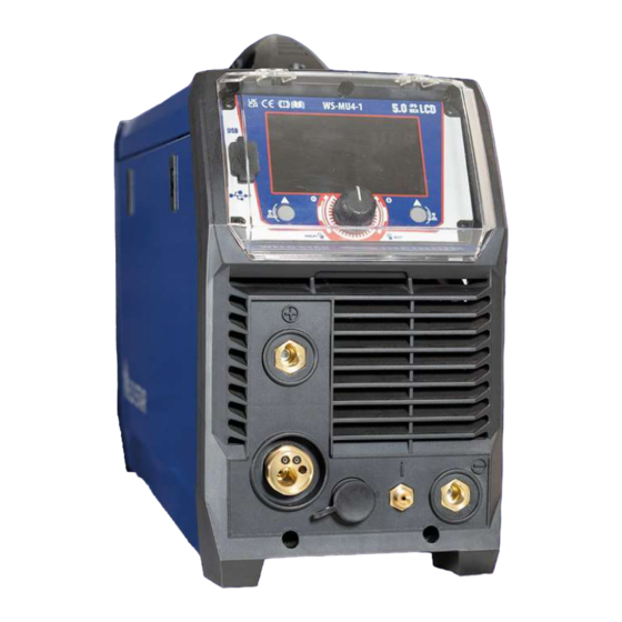
PRODUCT OVERVIEW The Weld Star MU4-1 is a true multi-process inverter welder offering professional welding performance in all processes and is the first of its kind to include pulse technology in MIG, TIG and MMA, making it the most versatile machine on the market today. It has been designed to incorporate the most advanced features and technology offering the operator a user-friendly interface via the 5”... -
Page 11: Product Technical Specifications
TECHNICAL SPECIFICATIONS Parameter Unit Weld Star WS-MU4-1 Wide Voltage 95Vac – 265Vac Rated input voltage AC110V (±15%) 50/60Hz AC230V (±15%) 50/60Hz Rated input power MIG 35 MIG 28 Rated input current Imax TIG AC 31.5 / DC 33 TIG AC 21 / DC 22.5 MMA AC 36.5 / DC 39.5... -
Page 12: Description Of Controls
10. Carry handle 11. Gas inlet 12. Air vent 13. Mains power ON/OFF switch 14. Mains input power cable Control panel view Weld Star WS-MU4-1 USB Connector * 5” Digital screen Left control button Main control dial and activation button... - Page 13 CONTROLS Side view Weld Star WS-MU4-1 15. Carry handle 16. Rear panel (see page 12 for further information). 17. Wire spool holder and tensioner: Allows a 5kg (200mm diameter) reel of wire to be located in place via an alignment pin and then locked in place with the locking nut. The spool holder also has a brake arrangement to ensure correct tension of the wire, this is done by turning the central bolt with an allen key clockwise (to tighten) or anti clockwise (to loosen).
-
Page 14: Installation Information
INSTALLATION Unpacking Check the packaging for any signs of damage. Carefully remove the machine and retain the packaging until the installation is complete. Location The machine should be located in a suitable position and environment. Care should be taken to avoid moisture, dust, steam, oil or corrosive gases. - Page 15 INSTALLATION MIG welding • Insert the welding torch (B) into the “Euro connector for torch in MIG” output socket on the front panel of the machine and tighten it into position. • Insert the work return lead cable plug (A) into the “-” output terminal of the welding machine and tighten by rotating it clockwise.
-
Page 16: Display Interface Explained
MULTIFUNCTIONAL DISPLAY WINDOW Display Screen Explained WS-MU4-1 Upon powering ON your MU4-1 and boot up sequence is complete, the main menu will appear on the LCD digital screen ’F’ as shown right, this allows the operator to navigate the various welding processes by rotating the control dial ‘B’... - Page 17 MULTIFUNCTIONAL DISPLAY WINDOW Display Screen Explained WS-MU4-1 (continued) As previously noted buttons A and C have 2 functions determined by either a short or long press of buttons A and C. • Briefly pressing buttons A or C will activate the 2 option icons circled purple.
-
Page 18: Operation - Mig/Mag
OPERATION - MIG/MAG Before starting any welding activity ensure that you have suitable eye protection and protective clothing. Also take the necessary steps to protect any persons within the welding area. MIG/MAG welding mode MIG - Metal Inert Gas Welding, MAG - Metal Active Gas Welding, GMAW - Gas Metal Arc Welding MIG welding was developed to help meet production demands of the war and post war economy which is an arc welding process in which a continuous solid wire electrode is fed through a MIG welding gun and... - Page 19 MULTIFUNCTIONAL DISPLAY WINDOW - MIG MODE Welding screen/display explained MU4-1 Upon powering ON your WS-MU4-1 and boot up is complete, the control panels main menu will appear on the digital panel as shown above. You can now navigate yourself though the various options and welding modes which include: Settings, MIG Pulse, MIG Synergic, MIG Manual, Lift TIG, HF TIG, Smart TIG and MMA.
- Page 20 MULTIFUNCTIONAL DISPLAY WINDOW - MIG MODE Welding screen/display explained MU4-1 When selecting either MIG pulse or MIG Synergic mode, the operator has the option to select material, gas and wire size as shown below, this selection is carried out by rotating and pressing the main dial to select the desired option.
- Page 21 MULTIFUNCTIONAL DISPLAY WINDOW - MIG MODE Welding screen/display explained MU4-1 When selecting MIG manual, you will be taken directly to the welding screen shown left. Now the left circular section offers just wire feed speed control and the right section shows voltage control, while the bottom row shows torch trigger mode and inductance control.
- Page 22 MULTIFUNCTIONAL DISPLAY WINDOW - MIG MODE Welding screen/display explained MU4-1 When selecting MIG mode you can select various trigger modes noted within the red circles below. Navigate to and highlight the lower bar central option (as circled below) as shown as 4T trigger mode. Depending on which welding mode you are in, will determine which options you can select.
-
Page 23: Operation - Tig
OPERATION - TIG Before starting any welding activity ensure that you have suitable eye protection and protective clothing. Also take the necessary steps to protect any personnel within the welding area. TIG welding mode Terms used: TIG – Tungsten Inert Gas, GTAW – Gas Tungsten Arc Welding. TIG welding is an arc welding process that uses a non-consumable tungsten electrode to produce the heat for welding. - Page 24 MULTIFUNCTIONAL DISPLAY WINDOW - TIG MODE Welding screen/display explained MU4-1 Upon powering ON your MU4-1 and boot up is complete, the control panels main menu will appear on the digital panel as shown above. You can now navigate yourself through the various options and welding modes which include: Settings, MIG Pulse, MIG Synergic, MIG Manual, Lift TIG, HF TIG, TIG and MMA.
- Page 25 MULTIFUNCTIONAL DISPLAY WINDOW - TIG MODE Welding screen/display explained MU4-1 When selecting LIFT TIG or HF TIG, you will be taken directly to the welding screen shown below. Note that the left circular section offers TIG welding current control and the right section shows TIG voltage, while the bottom row shows Pulse, torch trigger mode and DC/AC output selection.
- Page 26 MULTIFUNCTIONAL DISPLAY WINDOW - TIG MODE Welding screen/display explained MU4-1 Whether you have previously selected LIFT TIG, HF TIG or Smart TIG, the selection and setting of advanced welding parameters can be carried out in the welding interface screen by pressing the right button to enter the welding parameter setting interface.
- Page 27 MULTIFUNCTIONAL DISPLAY WINDOW - TIG MODE Welding screen/display explained MU4-1 Depending on which welding mode you are in, will determine which options you can select. As with previous pages, to select a different trigger option, press the control dial until the 2T tigger mode (shown in the image right) is highlighted red and then rotate the dial to select with trigger option you require, pressing...
- Page 28 MULTIFUNCTIONAL DISPLAY WINDOW - TIG MODE Welding screen/display explained MU4-1 Additional TIG features continued MIX AC/DC AC wave in AC/DC, this parameter serves to set the AC wave percentage with respect to the DC current output. The consequences of a higher value: •...
-
Page 29: Operation - Mma
OPERATION - MMA Before starting any welding activity ensure that you have suitable eye protection and protective clothing. Also take the necessary steps to protect any personnel within the welding area. MMA welding mode MMA (Manual Metal Arc), SMAW (Shielded Metal Arc Welding) or just Stick Welding. - Page 30 MULTIFUNCTIONAL DISPLAY WINDOW - MMA MODE Welding screen/display explained MU4-1 Upon powering ON your MU4-1 and boot up is complete, the control panels main menu will appear on the digital panel as shown above, rotate the control dial until the MMA welding option is center and then press the dial to access this welding mode.
- Page 31 MULTIFUNCTIONAL DISPLAY WINDOW - MMA MODE Welding screen/display explained MU4-1 MMA Welding parameter adjustments The image to the right shows the process flow of MMA welding, Hot Start current with hot start time, if AC is selected then AC frequency and AC duty is adjustable as shown as well as other parameters.
-
Page 32: Guide To Mig/Mag Welding
GUIDE TO MIG/MAG WELDING Before starting any welding activity ensure that you have suitable eye protection and protective clothing. Also take the necessary steps to protect any personnel within the welding area. MIG process description The MIG process was first patented for the welding of aluminium in 1949 in the USA. - Page 33 GUIDE TO MIG/MAG WELDING Before starting any welding activity ensure that you have suitable eye protection and protective clothing. Also take the necessary steps to protect any personnel within the welding area. Notes for the welding beginner This section is designed to give the beginner who has not yet done any welding some information to get them going.
- Page 34 GUIDE TO MIG/MAG WELDING Before starting any welding activity ensure that you have suitable eye protection and protective clothing. Also take the necessary steps to protect any personnel within the welding area. MIG controls The controls for the MIG/MAG systems are as follows. Controls can be electro mechanical or electronic but the effects will be the same.
- Page 35 GUIDE TO MIG/MAG WELDING Before starting any welding activity ensure that you have suitable eye protection and protective clothing. Also take the necessary steps to protect any personnel within the welding area. Burn back control In the event that the welder was to stop welding and all functions of the machine stopped simultaneously then the consumable filler wire would in all likelihood freeze in the weld pool.
- Page 36 MIG SETUP WELDING GUIDE Please Note: This information is intended to act as a guide only Low carbon steel, stainless steel pulse MAG welding process reference Welding Material Wire Welding Welding Welding Nozzle and Gas-flow position thickness diameter current voltage speed workpiece rate (L/MIN)
- Page 37 MIG SETUP WELDING GUIDE Please Note: This information is intended to act as a guide only Welding process of aluminum alloy pulse MIG welding process reference Welding Material Wire Welding Welding Welding Nozzle and Gas-flow position thickness diameter current voltage speed workpiece rate (L/MIN)
- Page 38 MIG WELDING PROBLEMS Before starting any welding activity ensure that you have suitable eye protection and protective clothing. Also take the necessary steps to protect any personnel within the welding area. MIG welding defects and prevention methods Defect Possible cause Action Porosity (within or outside the bead) Poor material Check the material is clean...
- Page 39 MIG WELDING PROBLEMS Before starting any welding activity ensure that you have suitable eye protection and protective clothing. Also take the necessary steps to protect any personnel within the welding area. MIG welding defects and prevention methods Defect Possible cause Action Burning through –...
- Page 40 MIG WELDING TORCH: Weld Star MU4-1 MIG Welding Torch Air Cooled - Model: T240 Rating 250A Co2 and 220A Mixed Gases @ 60% Duty Cycle, EN60974-7, Wire Size: 0.8mm to 1.2mm...
-
Page 41: Guide To Tig Welding
GUIDE TO DC TIG WELDING Before starting any welding activity ensure that you have suitable eye protection and protective clothing. Also take the necessary steps to protect any personnel within the welding area. DC welding Direct current welding is when the current flows in one direction only. Compared with AC welding the current once flowing will not go to zero until welding has ended. - Page 42 GUIDE TO DC TIG WELDING Before starting any welding activity ensure that you have suitable eye protection and protective clothing. Also take the necessary steps to protect any personnel within the welding area. Manual DC TIG Welding Amperage Guide- Mild Steel and Stainless Steel Base Metal Base Metal Tungsten...
- Page 43 GUIDE TO TIG WELDING Before starting any welding activity ensure that you have suitable eye protection and protective clothing. Also take the necessary steps to protect any personnel within the welding area. TIG torch body and components The torch body holds the various welding consumables in place as shown and is covered by a either a rigid phenolic or rubberised covering.
- Page 44 GUIDE TO TIG WELDING Before starting any welding activity ensure that you have suitable eye protection and protective clothing. Also take the necessary steps to protect any personnel within the welding area. TIG welding electrodes TIG welding electrodes are a ‘non consumable’ as it is not melted into the weld pool and great care should be taken not to let the electrode contact the welding pool to avoid weld contamination.
- Page 45 GUIDE TO TIG WELDING Before starting any welding activity ensure that you have suitable eye protection and protective clothing. Also take the necessary steps to protect any personnel within the welding area. TIG welding consumables The consumables of the TIG welding process are filler wires and shield gas. Filler wires Filler wires come in many different material types Filler Wire Diameter...
- Page 46 GUIDE TO TIG WELDING Before starting any welding activity ensure that you have suitable eye protection and protective clothing. Also take the necessary steps to protect any personnel within the welding area. Arc starting - lift TIG (lift arc) Not to be confused with scratch start, this arc starting method allows the tungsten to be in direct contact with the work piece first but with minimal current so as not to leave a tungsten deposit when the tungsten is lifted and an arc is established.
- Page 47 GUIDE TO AC TIG WELDING Before starting any welding activity ensure that you have suitable eye protection and protective clothing. Also take the necessary steps to protect any personnel within the welding area. AC TIG welding Alternating current, AC welding, is when the current once flowing will not go to zero until welding has ended, compared with DC welding when the current flows in one direction only.
- Page 48 GUIDE TO AC TIG WELDING Before starting any welding activity ensure that you have suitable eye protection and protective clothing. Also take the necessary steps to protect any personnel within the welding area. Manual AC TIG Welding Amperage Guide - Aluminium Material Base Metal Base Metal Tungsten...
- Page 49 GUIDE TO AC TIG WELDING Before starting any welding activity ensure that you have suitable eye protection and protective clothing. Also take the necessary steps to protect any personnel within the welding area. AC TIG welding square wave With the electronic development of inverter power sources, the square wave machine was developed. Due to these electronic controls the cross over from positive to negative and vice versa can be made almost in an instant which leads to more effective current in each half cycle due to a longer period at maximum.
- Page 50 GUIDE TO AC TIG WELDING Before starting any welding activity ensure that you have suitable eye protection and protective clothing. Also take the necessary steps to protect any personnel within the welding area. AC pulsed TIG welding Tc - Cathode current time Tp - AC period Tp - Pulsed peak current time T - Pulse period...
- Page 51 GUIDE TO AC TIG WELDING Before starting any welding activity ensure that you have suitable eye protection and protective clothing. Also take the necessary steps to protect any personnel within the welding area. AC Wave balance or cleaning control When welding materials with a refractory oxide surface such as aluminium this oxide needs to be removed to allow welding of the base material.
- Page 52 TIG WELDING TORCH: Weld Star MU4-1 TIG Welding Torch Air Cooled - Model TIG-103 Rating 200A DC, 150A AC @ 60% Duty Cycle EN60974-7 • 0.5mm to 4.0mm Electrodes Main Consumables Gas Lens Bodies Ceramic Cups for use with item 12 No Code Description No Code...
- Page 53 TIG WELDING PROBLEMS Before starting any welding activity ensure that you have suitable eye protection and protective clothing. Also take the necessary steps to protect any personnel within the welding area. TIG welding defects and prevention methods Defect Possible cause Action Excessive tungsten use Set up for DCEP...
- Page 54 TIG WELDING PROBLEMS Before starting any welding activity ensure that you have suitable eye protection and protective clothing. Also take the necessary steps to protect any personnel within the welding area. TIG welding defects and prevention methods Defect Possible cause Action Excessive bead build up, poor Weld current too low...
-
Page 55: Guide To Mma Welding
GUIDE TO MMA WELDING Before starting any welding activity ensure that you have suitable eye protection and protective clothing. Also take the necessary steps to protect any personnel within the welding area. Notes for the welding beginner This section is designed to give the beginner who has not yet done any welding some information to get them going. - Page 56 GUIDE TO MMA WELDING Before starting any welding activity ensure that you have suitable eye protection and protective clothing. Also take the necessary steps to protect any personnel within the welding area. MMA process tips and guides Typical welder set up 1.
- Page 57 GUIDE TO MMA WELDING Before starting any welding activity ensure that you have suitable eye protection and protective clothing. Also take the necessary steps to protect any personnel within the welding area. MMA arc striking Tap technique - Lift the electrode upright and bring it down to strike the work piece. After forming short circuit, quickly lift up about 2~4mm and arc will be ignited.
- Page 58 GUIDE TO MMA WELDING Before starting any welding activity ensure that you have suitable eye protection and protective clothing. Also take the necessary steps to protect any personnel within the welding area. Fillet welding The electrode should be positioned to split the angle i.e. 45º. Again the electrode should be inclined in the direction of travel at around 10º-30º.
- Page 59 MMA WELDING PROBLEMS Before starting any welding activity ensure that you have suitable eye protection and protective clothing. Also take the necessary steps to protect any personnel within the welding area. Arc welding defects and prevention methods Defect Possible cause Action Excessive spatter (beads of metal Amperage too high for the...
-
Page 60: Settings
MULTIFUNCTIONAL DISPLAY WINDOW - SETTINGS Welding screen/display explained MU4-1 The ‘Settings’ parameter adjustment section can be accessed by rotating the control dial (B) until the settings icon is front and centre (as image right shows) then press to enter the setting interface which is shown below. -
Page 61: Remote Control (Wired)
REMOTE CONTROL - WIRED The MU4-1 is supplied with a 9 pin remote control socket (early models were supplied with a 12 pin socket, see page 62) which is located on the front panel and is used to connect a TIG torch trigger with switch and/or torch mounted ‘analogue’... - Page 62 REMOTE CONTROL - WIRED Before starting any welding activity ensure that you have suitable eye protection and protective clothing. Also take the necessary steps to protect any personnel within the welding area. 12 Pin Remote control socket On earlier supplied MU4-1 machines a 12 pin remote control socket was fitted which was located on the front panel and is used to connect a TIG torch trigger with switch and/or torch mounted ‘analogue’...
-
Page 63: Remote Control (Wireless)
Also take the necessary steps to protect any personnel within the welding area. Wireless control The Weld Star WS-MU4-1 is equipped with in-built wireless technology and can accept a wireless remote foot current control signal from a wireless foot pedal which offers greater flexibility to the operator. -
Page 64: Maintenance
MAINTENANCE The following operation requires sufficient professional knowledge on electrical/electronic aspects and comprehensive safety knowledge. Make sure the input cable of the machine is disconnected from the electricity supply and wait for 5 minutes before removing the machine covers. In order to guarantee that the arc welding machine works efficiently and safely, it must be maintained regularly. -
Page 65: Troubleshooting
TROUBLESHOOTING The following operation requires sufficient professional knowledge on electrical/electronic aspects and comprehensive safety knowledge. Make sure the input cable of the machine is disconnected from the electricity supply and wait for 5 minutes before removing the machine covers. Before arc welding machines are dispatched from the factory, they have already been checked thoroughly. -
Page 66: Error Codes
ERROR CODES The following operation requires sufficient professional knowledge on electrical/electronic aspects and comprehensive safety knowledge. Make sure the input cable of the machine is disconnected from the electricity supply and wait for 5 minutes before removing the machine covers. Before arc welding machines are dispatched from the factory, they have already been checked thoroughly. -
Page 67: Electrical Schematic
ELECTRICAL SCHEMATIC The following operation requires sufficient professional knowledge on electrical/electronic aspects and comprehensive safety knowledge. Make sure the input cable of the machine is disconnected from the electricity supply and wait for 5 minutes before removing the machine covers. -
Page 68: Weee Disposal
And inspected according to following designated standards: - EN 60 974-1:2018+A1:2019 - EN 60 974-10:2014+A1:2015 Any alteration or change to these machines by any unauthorized person makes this declaration invalid. Model: Weld Star WS-MU4-1 ACDC Authorised Representative: Wilkinson Star Limited Shield Drive Wardley Industrial Estate... -
Page 70: Statement Of Warranty
STATEMENT OF WARRANTY All Weld Star welding, plasma multi-process machines sold through our partner Wilkinson Star Ltd within the United Kingdom, Ireland and Europe shall be warrantied to the original owner, non transferable, against failure due to defective materials or production. The warranty period is 5 years following the date of purchase. -
Page 71: Options And Accessories
OPTIONS AND ACCESSORIES Part Number Description T240-3 * MIG Torch 3mtr Euro T240-4 MIG Torch 4mtr Euro T240-5 MIG Torch 5mtr Euro WCS25-3LDT * Welding Cable Set (MMA) 3m WC-2-03LD Electrode Holder and Lead 3m EC-2-03LD Work Return Lead and Clamp 3m TIG-103 Titanium 26 TIG Torch 12.5ft c/w 12 pin plug and Dinse adaptor JE79-ERGO *... -
Page 72: Notes
NOTES _____________________________________ _____________________________________ _____________________________________ _____________________________________ _____________________________________ _____________________________________ _____________________________________ _____________________________________ _____________________________________ _____________________________________ _____________________________________ _____________________________________ _____________________________________ _____________________________________ _____________________________________ _____________________________________ _____________________________________ _____________________________________ _____________________________________ _____________________________________ _____________________________________... - Page 73 NOTES _____________________________________ _____________________________________ _____________________________________ _____________________________________ _____________________________________ _____________________________________ _____________________________________ _____________________________________ _____________________________________ _____________________________________ _____________________________________ _____________________________________ _____________________________________ _____________________________________ _____________________________________ _____________________________________ _____________________________________ _____________________________________ _____________________________________ _____________________________________ _____________________________________...
-
Page 74: Weld Star Contact Details
E&OE July 2023 Issue 4...
Need help?
Do you have a question about the WELD STAR WS-MU4-1 and is the answer not in the manual?
Questions and answers