Table of Contents
Advertisement
Advertisement
Table of Contents

Summary of Contents for TKE TW45
- Page 1 OPERATING MANUAL TW45 Drive 03/2023 6231003860...
- Page 2 "fireman". At the same time, it always refers to human genders: male, female, diverse. Issued by TK Aufzugswerke GmbH Bernhäuser Straße 45 73765 Neuhausen a. d. F. Germany Tel: +49 7158/12-0 E-mail: Doku.elevator.plant.de@tkelevator.com eli.tkelevator.com Internet: TK Elevator BA, TW45 | 6231003860 | 03/2023...
-
Page 3: Table Of Contents
Load data for upward horizontal / vertical rope pull direction.............. 34 4.1.9 Gear efficiency.............................. 35 4.1.10 Mass moment of inertia............................ 36 4.1.11 Weight................................... 36 4.1.12 Noise levels................................ 37 Dimensions................................. 38 4.2.1 Machine................................. 38 TK Elevator BA, TW45 | 6231003860 | 03/2023... - Page 4 ROBA-duplostop Size 125 brake - installation and operating manual.......... 79 10.2.4 mayr ROBA-duplostop Size 500 - 1800 brake - installation and operating manual...... 95 10.2.5 SKINTOP MS-SC Mounting instructions...................... 111 10.2.6 Wachendorff encoder WDG100H--xx-yyyy-ABN-I05-K3-D56 - assembly instructions..... 112 TK Elevator BA, TW45 | 6231003860 | 03/2023...
- Page 5 Table of contents 10.2.7 Drehgeber Wachendorf WDG 100H - Datenblatt.................. 113 10.2.8 Drehgeber Wachendorf WDG 100H-XX-YYYY - Montageanleitung............ 125 10.2.9 Drehgeber Wachendorf WDG 100H-38-2048.pdf.................. 126 TK Elevator BA, TW45 | 6231003860 | 03/2023...
-
Page 6: About These Instructions
Information must always be read and followed. Reference Chap. 1 P. 6 List ▪ Top item of a list – Sub-item of a list – Sub-item of a list ▪ Top item of a list ▪ Top item of a list TK Elevator BA, TW45 | 6231003860 | 03/2023... -
Page 7: Safety
Read and comply with the warning. 2.1.3 Indication of possible damage to property NOTICE Hazard with possible damage to property! May lead to product function impairments or function loss. Read and comply with the warning. TK Elevator BA, TW45 | 6231003860 | 03/2023... -
Page 8: Safety Requirements
Clearly establish all areas of responsibility prior to any activity. Always wear the personal protective equipment made available to you. Prior to work, make people aware of the dangers of electrical current. TK Elevator BA, TW45 | 6231003860 | 03/2023... -
Page 9: Dangers In Handling The Drive
▪ The elevator installation must ensure that emergency braking by the mechanical brake system takes place in the following cases: – Uncontrolled movement out of the stopping zone TK Elevator BA, TW45 | 6231003860 | 03/2023... -
Page 10: Warranty And Liability
▪ Read and comply with the document, in particular the chapter entitled "Safety", together with the warnings and all other applicable documents ▪ Comply with the commissioning instructions, the installation description as well as the required inspection and maintenance work TK Elevator BA, TW45 | 6231003860 | 03/2023... -
Page 11: 10 Rules For Health And Safety At Work
10 rules for health and safety at work 10 rules for health and safety at work The international rules for occupational health and safety can also be found https://eli.tkelevator.com/sup- on our internet platform ELI for download at: port/occupational-safety-health TK Elevator BA, TW45 | 6231003860 | 03/2023... -
Page 12: Personal Protective Equipment
▪ Flying parts ▪ Flying particles Eye injury Protective ▪ Laser beams goggles Loss of sight/blinding ▪ Emissions of optical rays Enable ▪ Electrical voltage Electric shock source of en- ergy TK Elevator BA, TW45 | 6231003860 | 03/2023... -
Page 13: Description
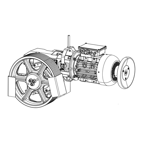
NBS – for machine location in the ma- chine room. ▪ Horizontal motor position; traction sheave position on left / on right; with / without emergency brake system, NBS – for machine location in the ma- chine room. TK Elevator BA, TW45 | 6231003860 | 03/2023... - Page 14 Brake release lever Motor terminal box, including in- termediate terminal connection Service brake for brake Encoder 10 Handwinding wheel Motor Installation in the machine room / vertical motor position IMV1 Fig. 2 ATR_2_21_0028_0 TK Elevator BA, TW45 | 6231003860 | 03/2023...
- Page 15 Oil level monitoring (gauge (R3/4") glass) Motor connection (M16x1.5 / M25x1.5) Traction sheave mounting (ten- sion disc with screwed connec- Brake connection tion) (2x M16x1.5) Mounting surface for machine 13 Transport eyebolts base frame TK Elevator BA, TW45 | 6231003860 | 03/2023...
- Page 16 Oil level monitoring (gauge (R3/4") glass) Motor connection (M16x1.5 / Traction sheave mounting (ten- M25x1.5) sion disc with screwed connec- tion) Brake connection (2 M16x1.5) Mounting surface for machine 13 Transport eyebolt base frame TK Elevator BA, TW45 | 6231003860 | 03/2023...
- Page 17 NBS Socket wrench for manual re- Screws for manual release lease (screw head marked in red) Brake test switch with connec- Connection line, brake voltage tion line Protective cover for brake TK Elevator BA, TW45 | 6231003860 | 03/2023...
- Page 18 Machine room with earthquake safeguard complying with EN81-77 (shown in the left traction sheave position / vertical motor position and earthquake safeguard complying with EN81-77) Fig. 6 ATR_2_12_0106_0 TK Elevator BA, TW45 | 6231003860 | 03/2023...
- Page 19 It is made available by TKE-NA. The components for the rope guard and the fastening elements for the ma- chine on the machine base frame are also made available by TKE-NA. The connection lines of the service and emergency brakes are routed through the enlarged motor terminal box and routed by means of conduits into a mo- tor interface box (MIB).
-
Page 20: Machine Base Frame
- counterweight ASL ≤ (DT + 100) mm with traction sheave diameter 520 or 590 mm ▪ Installations with rope suspension 2:1 and traction sheave diameters 440, 520, or 590 mm TK Elevator BA, TW45 | 6231003860 | 03/2023... - Page 21 The rope pulleys (versions, see product description of rope pulleys) are designed with maintenance-free roller bearings. Fig. 10 ATR_2_21_0040_0 Item Designation Item Designation TW45B M SR machine base TW45C machine frame Mounting parts for machine Insulation elements base frame TK Elevator BA, TW45 | 6231003860 | 03/2023...
- Page 22 The protection device consists of a modified rope guard for rope pulleys of diameter D360 or D450 which prevent the ropes departing from the grooves. Fig. 12 ATR_2_12_0156_0 TK Elevator BA, TW45 | 6231003860 | 03/2023...
-
Page 23: Motor Versions
(type 1024 HTL and type 1024 sine/cosine). An encoder with 2048 TTL and 3 m connection line is used for the ISIS1 (MRL). TK Elevator BA, TW45 | 6231003860 | 03/2023... -
Page 24: Special Versions
In the ISIS1 version, the NBS emergency brake also meets the requirements in accordance with ASME A17.1. Alongside the service brake, an additional braking device is fitted on the drive shaft, consisting of the components: ▪ Type-approved electromagnetic disc brake in accordance with Chap. 4.1.6 P. 32 TK Elevator BA, TW45 | 6231003860 | 03/2023... -
Page 25: Version With Earthquake Safeguard Complying With En81-77
3.3.7 Version for machine location in the shaft pit for ISIS1 This version is intended for TKE-NA. The machine is located in the shaft pit with upward vertical rope pull and is intended for a range of performance from 2100 lbs/100 fpm to 3000 lbs/200 fpm, with traction sheave 10.5 in (D267 mm) and rope attachment 2:1 in each case. -
Page 26: Combination Of Versions / Options
440 / 520 / 590 traction sheave versions NBS Version with emergency brake-NBS EN81-77 Version with earthquake protection in accordance with EN81-77 ISIS1 Delivery version for ISIS1 / SA1 version with modified fastening TK Elevator BA, TW45 | 6231003860 | 03/2023... -
Page 27: Technology
TW45C Axle distance [mm] Gear ratio 40:3/41:2/32:1/46:1/32:3 Oil filling, motor po- sition Synthetic gear oil (polyalkylene glycol with ad- Oil grade ditives) Designation Backlash [°] 0.03-0.07 Weight [kg] approx. 105 Tab. 2 ATR_1_21_0005_0 TK Elevator BA, TW45 | 6231003860 | 03/2023... -
Page 28: Brake
This brake is also used for the ISIS1 version with the machine in the shaft pit, but in an adapted version with altered voltage and without a manual release lever. With ASME A17.1, the brake is regarded as 100 Nm (2x50 Nm). TK Elevator BA, TW45 | 6231003860 | 03/2023... -
Page 29: Encoder
TW45C-RSO500/1200 Nm Test number: LR 34805 Tab. 4 ATR_1_21_0040_0 1) DC - direct current cut-off (emergency stop). 2) Complying with EN81-20/50. 3) Complying with EN81-1:1998+A3:2009. 4.1.3 Encoder The following hollow shaft encoders are available: TK Elevator BA, TW45 | 6231003860 | 03/2023... -
Page 30: Traction Sheave
With minimum groove clearance - RAmin - in accordance with product description for groove profiles for seat grooves (for vee grooves, if deviating). TKE-NA provides a D267 mm traction sheave for the ISIS1 (MRL) version (not in the scope of supply of TK Aufzugswerke GmbH). - Page 31 1300 32:1 0.63 1600 1050 1500 1120 41:2 1200 1400 1420 1350 1050 1210 1350 0.80 0.80 1500 1060 41:2 1400 40:3 1050 1500 1300 1780 1.00 41:2 1.00 1400 1510 1250 TK Elevator BA, TW45 | 6231003860 | 03/2023...
-
Page 32: Motor Versions
The machines are conceived for a service life of at least 15 years and/or 20,000 hours of operation. 4.1.6 Motor versions Standard versions of motors Designation Unit Technical data Manufacturer EME (CEG) Type MT132STD MT132STD TK Elevator BA, TW45 | 6231003860 | 03/2023... - Page 33 Rated torque [Nm] 36.4 36.0 33.8 49.2 49.1 46.1 72.8 71.9 67.5 20.4// 27.2// 39.0// Rated current 21.0//10.5 28.0//14.0 41.0//20.5 10.2 13.6 19.5 max. starting torque [Nm] Max. starting current 42//21 56//28 86//43 TK Elevator BA, TW45 | 6231003860 | 03/2023...
-
Page 34: Load Data - Traction Sheave Shaft
TW45C with vertical motor position ▪ Horizontal rope pull: Ft = 76 kN ≤ Ft zul-stat stat-max ▪ Upward vertical rope pull: Ft = 56 kN ≤ Ft zul-stat stat-max TK Elevator BA, TW45 | 6231003860 | 03/2023... -
Page 35: Gear Efficiency
1250 -1800 800 - 1249 1250 -1800 1250 -1800 46:1 0.68 0.70 0.70 0.72 0.73 0.39 -0.08 32:1 0.72 0.74 0.74 0.76 0.77 0.46 0.18 41:2 0.80 0.82 0.82 0.84 0.85 0.56 0.47 TK Elevator BA, TW45 | 6231003860 | 03/2023... -
Page 36: Mass Moment Of Inertia
▪ E 11.0 m = 245 kg The overall mass for versions of the machine not listed in the table is to be de- termined according to the weight data of the individual components. TK Elevator BA, TW45 | 6231003860 | 03/2023... -
Page 37: Noise Levels
TW45C with operation at normal rating are: Version [dB(A)] Motor speed n1 approx. 63 ≤ 1250 rpm TW45C approx. 65 ≤ 1500 rpm approx. 67 ≤ 1800 rpm Tab. 14 ATR_1_21_0015_0 ATR_1_22_032_0 TK Elevator BA, TW45 | 6231003860 | 03/2023... -
Page 38: Dimensions
Machine room version / vertical motor position Fig. 15 ATR_2_21_0034_0 Item Designation Item Designation Screwed connections - machine base frame with DT = 440 / 520 / 590 M16 -8.8 Manual brake release for Mayr brake RSZ125-2x50 Nm TK Elevator BA, TW45 | 6231003860 | 03/2023... - Page 39 Screwed connections - machine base frame verted to A-A M16 -8.8 with DT = 440 / 520 / 590 Manual brake release for Mayr brake Clearance for manual release of the emer- RSZ125-2x50 Nm gency brake, NBS TK Elevator BA, TW45 | 6231003860 | 03/2023...
- Page 40 Technology Dimensions ISIS1 version (MRL – machine in the shaft pit) Fig. 17 ATR_2_12_0152_0 TK Elevator BA, TW45 | 6231003860 | 03/2023...
- Page 41 Technology Dimensions Machine room version with horizontal rope departure direction Fig. 18 ATR_2_12_0153_0 (Adjustable range of the upper rope guard +/- 15° to the horizontal) TK Elevator BA, TW45 | 6231003860 | 03/2023...
-
Page 42: Machine Base Frame
Project planning dimensions: Project planning dimen- Traction sheave version Unit Machine arrangement sion left right (mm) (mm) Tab. 15 ATR_1_21_0019_0 Intermediate values for x1 and x2 in the modular dimension of 40 mm possible TK Elevator BA, TW45 | 6231003860 | 03/2023... - Page 43 Technology Dimensions Machine base frame with rope pulley - right-hand version of the rope pulley position Fig. 20 ATR_2_21_0042_0 TK Elevator BA, TW45 | 6231003860 | 03/2023...
- Page 44 154 616 (°) Tab. 16 ATR_1_21_0020_0 Intermediate values for ASL in the modular dimension of 40 mm possible. Distances: Rope pulley version Unit Project planning dimension (mm) D360 (mm) D450 (mm) Tab. 17 ATR_1_21_0021_0 TK Elevator BA, TW45 | 6231003860 | 03/2023...
- Page 45 Diameter of traction D360 D450 sheave Dt [mm] α α α α min max max min min max max min (mm) / 149 576 168 (°) (mm) / 154 616 (°) Tab. 18 ATR_1_21_0020_0 TK Elevator BA, TW45 | 6231003860 | 03/2023...
- Page 46 Technology Dimensions Intermediate values for ASL in the modular dimension of 40 mm possible. Distances: Rope pulley version Unit Project planning dimension (mm) D360 (mm) D450 (mm) Tab. 19 ATR_1_21_0021_0 TK Elevator BA, TW45 | 6231003860 | 03/2023...
-
Page 47: Transportation And Storage
Observe the symbols attached to the packaging or in visible locations. Dispose of used packing material in an environmentally responsible man- ner. Specific transport equipment and shipping braces remain with the customer. TK Elevator BA, TW45 | 6231003860 | 03/2023... -
Page 48: Transport
5. In the case of a machine that is mounted on the machine base frame, at- tach a transport rope to the base frame. TK Elevator BA, TW45 | 6231003860 | 03/2023... -
Page 49: Checking The Delivery
Severe transport damage to the product. Can lead to a malfunction of the product and thus to death or serious injury. Before commissioning, ensure that there is no severe damage to the product. TK Elevator BA, TW45 | 6231003860 | 03/2023... -
Page 50: Intermediate Storage
– Protect it against the formation of condensation and moisture. – Protect against dirt in the machine. In the case of downtimes of longer than 1 year, carry out standstill main- tenance Chap. 9.1 P. 74. TK Elevator BA, TW45 | 6231003860 | 03/2023... -
Page 51: Installation
SA9 traction sheave in the shaft, machine with extended traction sheave shaft and pedestal bearing. 1. Fitting and mounting of the compensation supports. 2. Horizontal alignment of the traction sheave shaft. 3. Align the bearings of the machine and the outside bearing exactly. TK Elevator BA, TW45 | 6231003860 | 03/2023... -
Page 52: Mounting The Frame With Rope Pulley
Use a spirit level to check; add support if necessary. Secure the drive on the machine base frame against shifting with ad- justing screws or stops. Arrange the suspension ropes symmetrically on the suspension plate, traction sheave and rope pulleys. TK Elevator BA, TW45 | 6231003860 | 03/2023... - Page 53 2. Loosely assemble the supplied frame in the machine room. 3. Mount the supports with additional drilled holes and pulley support on the side of the diverter pulley. 4. Mount and secure the diverter pulley with axle on the pulley supports. TK Elevator BA, TW45 | 6231003860 | 03/2023...
-
Page 54: Mounting The Rope Guard
(machine arrangement up/down beside), an additional rope guard is required to prevent foreign bodies entering between the rope and groove. If the rope run-in zone is protected within the machine base frame, the function "protection against injury" is not required. TK Elevator BA, TW45 | 6231003860 | 03/2023... -
Page 55: Rope Pulley On The Machine Base Frame
▪ Insulation elements without underlay for machine room without floor pavement ▪ Insulation elements with underlay for machine room with floor pavement (≤ 60 mm height); support made from Multiplex laminated wood 140x140x80 mm. TK Elevator BA, TW45 | 6231003860 | 03/2023... -
Page 56: Electrical Connection
Earth the motor and brake magnet in accordance with country-specific regulations. Electrical connections must correspond to at least the protection class in accordance with the name plate and/or required country-specific protec- tion class. TK Elevator BA, TW45 | 6231003860 | 03/2023... -
Page 57: Connecting The Machine
Representation in star circuit Υ and various versions. If necessary, reconnect in delta section Δ according to wiring diagram Fig. 28 ATR_2_21_0052_0 Item Designation Item Designation Connection for PE conductor Posistor temperature sensor Posistor temperature sensor TK Elevator BA, TW45 | 6231003860 | 03/2023... -
Page 58: Connecting The Motor Line
5. Pull the shielding braid evenly over the lamellar insert. 6. The braid must not protrude beyond the lamellar insert into the thread. 7. Pull the cable through the cap nut. 8. Push the cap nut over the shielding. TK Elevator BA, TW45 | 6231003860 | 03/2023... -
Page 59: Connecting The Posistor
If the emergency brake system is fitted, a description with all the details regard- ing connection and operation of the emergency brake can be found in the sep- arately enclosed operating manual for the emergency brake system, NBS. TK Elevator BA, TW45 | 6231003860 | 03/2023... -
Page 60: Work On The Product
8. Connect the measuring device to the 2nd brake circuit. 9. Repeat the test operation on the 2nd brake circuit. 10. Re-establish the original state of the circuit (operation of both brakes sim- ultaneously). TK Elevator BA, TW45 | 6231003860 | 03/2023... -
Page 61: Replacing The Brake
When the wear limit (1.0 mm / gap) is reached or there is a defect in the brake, the complete brake is to be replaced in all cases. 1. Installation and removal, see Chap. 10 P. 75. TK Elevator BA, TW45 | 6231003860 | 03/2023... - Page 62 Return spring for manual release Switch bracket for manual re- with mounting parts lease with mounting parts Switch bracket for manual re- Manual release lever with lease with mounting parts mounting parts TK Elevator BA, TW45 | 6231003860 | 03/2023...
-
Page 63: Checking The Oil Level
Long-term car operation heats up the oil! During work on the drive, wait until the housing has cooled down, if ne- cessary. 1. Heat the gear to operating temperature (approx. 35°C) before replacing. TK Elevator BA, TW45 | 6231003860 | 03/2023... - Page 64 13. TK Aufzugswerke GmbH will not be held liable for damage resulting from the use of non-approved lubricants. Vertical motor position Fig. 33 ATR_2_12_0059_0 Item Designation Item Designation Ventilation, filling opening Oil gauge glass Oil drain TK Elevator BA, TW45 | 6231003860 | 03/2023...
-
Page 65: Checking The Backlash
9. Turn the traction sheave by hand until the dial gauge pointer moves. 10. Move the traction sheave back and forth until resistance is felt. 11. Read off the dial gauge (ME). TK Elevator BA, TW45 | 6231003860 | 03/2023... -
Page 66: Replacing The Traction Sheave
4. Remove the fastening screws with tension disc. 5. Insert the fastening screw in the tension disc the other way around. 6. Screw the threaded rod into holes for forcing. 7. Tighten threaded rods alternately. TK Elevator BA, TW45 | 6231003860 | 03/2023... - Page 67 1. Release the mounting of the traction sheave from the lifting gear. 2. Hang up the ropes on the traction sheave. 3. Fit the rope guard plates. 4. Align the rope guard plates. 5. Remove the securing devices from the car and counterweight. TK Elevator BA, TW45 | 6231003860 | 03/2023...
-
Page 68: Replacing The Motor
12. Make the electrical connections as per terminal connecting plan Installa- tion. 13. Establish the connections of the brake and encoder to the control system. 14. Check the function of the brake before commissioning. TK Elevator BA, TW45 | 6231003860 | 03/2023... -
Page 69: Replacing The Encoder
4. Screw on the encoder mount at the motor. 5. Secure the encoder inner ring by tightening the stud on the motor shaft. 6. Push the handwinding wheel with hub onto the shaft end. TK Elevator BA, TW45 | 6231003860 | 03/2023... -
Page 70: Checking For Grease/Oil Leakage
If necessary, check on a daily basis whether oil/grease is still leaking. If this is the case: Shut down installa- tion. Tab. 21 ATR_00_0004_0 See manufacturer's instructions Chap. 10 P. 75 TK Elevator BA, TW45 | 6231003860 | 03/2023... -
Page 71: Blocking Clamp
The blocking clamp is to be pre-tensioned by evenly tightening the two hexagon nuts until it is excluded that ropes will slip. Fig. 38 ATR_2_12_0066_0 Item Designation Item Designation Traction sheave Ropes Pressure piece Washer Hexagon nut Spacer sleeve Clamp clip TK Elevator BA, TW45 | 6231003860 | 03/2023... -
Page 72: Commissioning
In the event of uncontrolled elevator car movement, let go of the hand- winding wheel immediately. 1. Open the brake; move the brake release lever into its operating position. TK Elevator BA, TW45 | 6231003860 | 03/2023... - Page 73 Comply with the separate NBS operat- ing manual. The operating manual for machines with emergency brake system equipment is delivered separately. Emergency brake system, NBS. Brake release lever for manual release of machines with Mayr brake Chap. 10 P. 75 TK Elevator BA, TW45 | 6231003860 | 03/2023...
-
Page 74: Maintenance
15. Check that protective and safety devices are present and correctly set. 16. Check the seals at the shaft in the area of the brake and at the bearing for grease and/or oil leakage. TK Elevator BA, TW45 | 6231003860 | 03/2023... -
Page 75: Appendix
Tightness 10.9 12.9 Screw/bolt size Tightening torque [Nm] 1080 1300 1800 2150 Tab. 22 ASY_1_00_0001_0 10.2 Manufacturer information Also see about this Wachendorff encoder WDG100H_38-1024 - Data sheet P. 77 TK Elevator BA, TW45 | 6231003860 | 03/2023... -
Page 76: Verification Of Traction Sheave Calculation
P. 95 SKINTOP MS-SC Mounting instructions P. 111 Wachendorff encoder WDG100H--xx-yyyy-ABN-I05-K3-D56 - assembly instructions P. 112 Drehgeber Wachendorf WDG 100H - Datenblatt P. 113 Drehgeber Wachendorf WDG 100H-XX-YYYY - Montageanleitung P. 125 Drehgeber Wachendorf WDG 100H-38-2048.pdf P. 126 TK Elevator BA, TW45 | 6231003860 | 03/2023... - Page 77 Wachendorff Automation GmbH & Co. KG Industriestrasse 7 D-65366 Geisenheim Tel.: +49 (0) 67 22 / 99 65 - 25 Fax: +49 (0) 67 22 / 99 65 - 70 www.wachendorff.de Hollow shaft Encoder WDG 100H Specifications Mechanical Data Housing - Servo flange: Aluminium - Housing:...
- Page 79 Installation and Operational Instructions for ROBA-stop -Z Type 892.101.0 ® Size 125 (E073 01 046 000 4 EN) Translation of the Original Operational Instructions Design according to Drawing number: E073 01 046 000 1 10 Article number: 8227821 Drawing number: E073 01 046 000 1 11 Article number: 8253118 (without hub (12)) Drawing number: E073 01 046 000 1 12 Article number: 8292346 (without hand release (18))
- Page 80 Installation and Operational Instructions for ROBA-stop -Z Type 892.101.0 ® Size 125 (E073 01 046 000 4 EN) Guidelines on the Declaration of Conformity A conformity evaluation has been carried out for the product (electromagnetic safety brake) in terms of the EU Low Voltage Directive 2014/35/EU and the RoHS 2011/65/EU with 2015/863/EU.
- Page 81 Installation and Operational Instructions for ROBA-stop -Z Type 892.101.0 ® Size 125 (E073 01 046 000 4 EN) Safety Regulations These Safety Regulations are user hints only and may not be complete! General Guidelines Guidelines for Electromagnetic Compatibility (EMC) DANGER In accordance with the EMC directive 2014/30/EU, the individual Danger of death! components produce no emissions.
- Page 82 Installation and Operational Instructions for ROBA-stop -Z Type 892.101.0 ® Size 125 (E073 01 046 000 4 EN) Safety Regulations These Safety Regulations are user hints only and may not be complete! Dimensioning Intended Use Attention! This safety brake is intended for use in electrically operated When dimensioning the brake, please take into consideration elevators and goods elevators.
- Page 83 Installation and Operational Instructions for ROBA-stop -Z Type 892.101.0 ® Size 125 (E073 01 046 000 4 EN) Safety Regulations These Safety Regulations are user hints only and may not be complete! User-implemented Protective Measures: EN ISO 12100 Safety of machinery – General principles for design - Risk assessment ...
- Page 84 Installation and Operational Instructions for ROBA-stop -Z Type 892.101.0 ® Size 125 (E073 01 046 000 4 EN) 18.3 18.5 18.4 21/22 18.1 18.3 18.2 18.7 18.9/18.10 18.6 18.6 18.7 18.8/18.11 18.2 Fig. 1 Fig. 2 Fig. 3 11.4 11.3 Installation dimension 115 +1 mm 11.2...
- Page 85 Installation and Operational Instructions for ROBA-stop -Z Type 892.101.0 ® Size 125 (E073 01 046 000 4 EN) Parts List (Only use mayr original parts) Item Name Pcs. O-ring D60 x 3 Set screw M6 x 10 Brake body Magnetic coil Cap screw M8 x 85...
- Page 86 Installation and Operational Instructions for ROBA-stop -Z Type 892.101.0 ® Size 125 (E073 01 046 000 4 EN) Table 1: Technical Data Article number 8227821 8253118 8292346 Nominal voltage 90 V 90 V 55 V Overexcitation voltage 180 V 180 V 110 V Coil power (nominal power at 20°C) 76 W...
- Page 87 Installation and Operational Instructions for ROBA-stop -Z Type 892.101.0 ® Size 125 (E073 01 046 000 4 EN) Application Installation Conditions ROBA-stop ® -Z brake for use as a holding brake with The eccentricity of the shaft end in relation to the mounting ...
- Page 88 Installation and Operational Instructions for ROBA-stop -Z Type 892.101.0 ® Size 125 (E073 01 046 000 4 EN) Installation Mount plastic hoses (17) onto both headless screws (16) in All the screws (except the cap screw Item 21) order to dampen vibration noises. and the set screws mounted by the customer must be tightened using the tightening torque Insert the elastomeric element (13) in the claws of the hub...
- Page 89 Installation and Operational Instructions for ROBA-stop -Z Type 892.101.0 ® Size 125 (E073 01 046 000 4 EN) Electrical Connection and Wiring Magnetic Field Removal AC-side switching In safety applications, the rules for risk minimisation and error avoidance (e.g. redundance, diversity, resistance, monitoring etc.) The power circuit is interrupted must be observed during electrical activation.
- Page 90 Installation and Operational Instructions for ROBA-stop -Z Type 892.101.0 ® Size 125 (E073 01 046 000 4 EN) Permitted Shaft Misalignments Shaft Alignment ROBA ® -ES coupling compensates for radial, axial and angular Exact alignment of the shafts improves the running smoothness shaft misalignments (Fig.
- Page 91 Installation and Operational Instructions for ROBA-stop -Z Type 892.101.0 ® Size 125 (E073 01 046 000 4 EN) Braking Torque Dual Circuit Brake Functional Inspection The (nominal) braking torque is the torque effective in the shaft The ROBA-stop ® –Z brake is equipped with a double safety train on slipping brakes, with a sliding speed of 1 m/s referring to (redundant) braking system.
- Page 92 Installation and Operational Instructions for ROBA-stop -Z Type 892.101.0 ® Size 125 (E073 01 046 000 4 EN) Release Monitoring Customer-side Inspection after Attachment The brakes are supplied with manufacturer-side installed and adjusted release monitoring device. For customer-side connection as NO contact. The microswitch (11.1) emits a signal for every brake condition Brake de-energized ...
- Page 93 Installation and Operational Instructions for ROBA-stop -Z Type 892.101.0 ® Size 125 (E073 01 046 000 4 EN) Maintenance Replacing the Rotors (5 and 6) Before Replacing the Rotors ROBA-stop ® –Z brakes are mainly maintenance-free. The friction lining pairing is robust and wear-resistant. This ensures a Cleaning of the brake.
- Page 94 Installation and Operational Instructions for ROBA-stop -Z Type 892.101.0 ® Size 125 (E073 01 046 000 4 EN) Disposal Guidelines on the WEEE Directive 2012/19/EU Our electromagnetic brake components must be disposed of separately as they consist of different materials. Please also Avoidance of waste from electrical and electronic devices and the observe the relevant authority regulations.
- Page 95 Installation and Operational Instructions for ROBA-stop -Z Type 892.101.0 ® Size 125 (E073 01 046 000 4 EN) Translation of the Original Operational Instructions Design according to Drawing number: E073 01 046 000 1 10 Article number: 8227821 Drawing number: E073 01 046 000 1 11 Article number: 8253118 (without hub (12)) Drawing number: E073 01 046 000 1 12 Article number: 8292346 (without hand release (18))
- Page 96 Installation and Operational Instructions for ROBA-stop -Z Type 892.101.0 ® Size 125 (E073 01 046 000 4 EN) Guidelines on the Declaration of Conformity A conformity evaluation has been carried out for the product (electromagnetic safety brake) in terms of the EU Low Voltage Directive 2014/35/EU and the RoHS 2011/65/EU with 2015/863/EU.
- Page 97 Installation and Operational Instructions for ROBA-stop -Z Type 892.101.0 ® Size 125 (E073 01 046 000 4 EN) Safety Regulations These Safety Regulations are user hints only and may not be complete! General Guidelines Guidelines for Electromagnetic Compatibility (EMC) DANGER In accordance with the EMC directive 2014/30/EU, the individual Danger of death! components produce no emissions.
- Page 98 Installation and Operational Instructions for ROBA-stop -Z Type 892.101.0 ® Size 125 (E073 01 046 000 4 EN) Safety Regulations These Safety Regulations are user hints only and may not be complete! Dimensioning Intended Use Attention! This safety brake is intended for use in electrically operated When dimensioning the brake, please take into consideration elevators and goods elevators.
- Page 99 Installation and Operational Instructions for ROBA-stop -Z Type 892.101.0 ® Size 125 (E073 01 046 000 4 EN) Safety Regulations These Safety Regulations are user hints only and may not be complete! User-implemented Protective Measures: EN ISO 12100 Safety of machinery – General principles for design - Risk assessment ...
- Page 100 Installation and Operational Instructions for ROBA-stop -Z Type 892.101.0 ® Size 125 (E073 01 046 000 4 EN) 18.3 18.5 18.4 21/22 18.1 18.3 18.2 18.7 18.9/18.10 18.6 18.6 18.7 18.8/18.11 18.2 Fig. 1 Fig. 2 Fig. 3 11.4 11.3 Installation dimension 115 +1 mm 11.2...
- Page 101 Installation and Operational Instructions for ROBA-stop -Z Type 892.101.0 ® Size 125 (E073 01 046 000 4 EN) Parts List (Only use mayr original parts) Item Name Pcs. O-ring D60 x 3 Set screw M6 x 10 Brake body Magnetic coil Cap screw M8 x 85...
- Page 102 Installation and Operational Instructions for ROBA-stop -Z Type 892.101.0 ® Size 125 (E073 01 046 000 4 EN) Table 1: Technical Data Article number 8227821 8253118 8292346 Nominal voltage 90 V 90 V 55 V Overexcitation voltage 180 V 180 V 110 V Coil power (nominal power at 20°C) 76 W...
- Page 103 Installation and Operational Instructions for ROBA-stop -Z Type 892.101.0 ® Size 125 (E073 01 046 000 4 EN) Application Installation Conditions ROBA-stop ® -Z brake for use as a holding brake with The eccentricity of the shaft end in relation to the mounting ...
- Page 104 Installation and Operational Instructions for ROBA-stop -Z Type 892.101.0 ® Size 125 (E073 01 046 000 4 EN) Installation Mount plastic hoses (17) onto both headless screws (16) in All the screws (except the cap screw Item 21) order to dampen vibration noises. and the set screws mounted by the customer must be tightened using the tightening torque Insert the elastomeric element (13) in the claws of the hub...
- Page 105 Installation and Operational Instructions for ROBA-stop -Z Type 892.101.0 ® Size 125 (E073 01 046 000 4 EN) Electrical Connection and Wiring Magnetic Field Removal AC-side switching In safety applications, the rules for risk minimisation and error avoidance (e.g. redundance, diversity, resistance, monitoring etc.) The power circuit is interrupted must be observed during electrical activation.
- Page 106 Installation and Operational Instructions for ROBA-stop -Z Type 892.101.0 ® Size 125 (E073 01 046 000 4 EN) Permitted Shaft Misalignments Shaft Alignment ROBA ® -ES coupling compensates for radial, axial and angular Exact alignment of the shafts improves the running smoothness shaft misalignments (Fig.
- Page 107 Installation and Operational Instructions for ROBA-stop -Z Type 892.101.0 ® Size 125 (E073 01 046 000 4 EN) Braking Torque Dual Circuit Brake Functional Inspection The (nominal) braking torque is the torque effective in the shaft The ROBA-stop ® –Z brake is equipped with a double safety train on slipping brakes, with a sliding speed of 1 m/s referring to (redundant) braking system.
- Page 108 Installation and Operational Instructions for ROBA-stop -Z Type 892.101.0 ® Size 125 (E073 01 046 000 4 EN) Release Monitoring Customer-side Inspection after Attachment The brakes are supplied with manufacturer-side installed and adjusted release monitoring device. For customer-side connection as NO contact. The microswitch (11.1) emits a signal for every brake condition Brake de-energized ...
- Page 109 Installation and Operational Instructions for ROBA-stop -Z Type 892.101.0 ® Size 125 (E073 01 046 000 4 EN) Maintenance Replacing the Rotors (5 and 6) Before Replacing the Rotors ROBA-stop ® –Z brakes are mainly maintenance-free. The friction lining pairing is robust and wear-resistant. This ensures a Cleaning of the brake.
- Page 110 Installation and Operational Instructions for ROBA-stop -Z Type 892.101.0 ® Size 125 (E073 01 046 000 4 EN) Disposal Guidelines on the WEEE Directive 2012/19/EU Our electromagnetic brake components must be disposed of separately as they consist of different materials. Please also Avoidance of waste from electrical and electronic devices and the observe the relevant authority regulations.
- Page 111 U.I.LAPP GmbH GEBRAUCHSANWEISUNG SKINTOP® MS-M, MSR-M, MS-M-XL, MSR-M-XL Schulze-Delitzsch-Straße 25 MS-SC-M, MS-SC-M-XL D-70565 Stuttgart INSTRUCTION SHEET Tel.0711/7838-1010 Fax.0711/7838-2640 Internet:www.lappkabel.de Klemm- und Dichtbereich Clamping and Sealing range Approbationen Bezeichnung Approvals Product EN 50262 UL 514 B Größe/Size Kat.der Anzugsdreh- Klemm- Diameter ∅...
- Page 112 Wachendorff Automation GmbH & Co. KG Industriestraße 7 • D-65366 Geisenheim WDG100H-xx-yyyy-ABN-I05-K3-D56-zzz Tel.: +49(0)672 2 /99 65 -25 xx = Ø 25, 25.4, 28, 30, 38, 40, 42, 45 Fax: +49(0)672 2 /99 65-70 yyyy = PPR = 1024, 2048, 4096 eMail: wdg@wachendorff.de zzz = 130 = 13m, 200 = 20m, blank = 10m www.wachendorff-automation.de...
- Page 113 Drehgeber WDG 100H www.wachendorff-automation.de/wdg100h Wachendorff Automation ... Systeme und Drehgeber • Komplette Systeme • Industrierobuste Drehgeber für Ihren Anwendungsfall • Standardprogramm und Kundenversionen • Höchste zulässige Lasten • 48 Stunden Eilproduktion • Fertigung in Deutschland • Weltweites Distributoren-Netzwerk WDG 100H Alle Angaben ohne Gewähr, Irrtümer und Änderungen vorbehalten. © Wachendorff Automation GmbH & Co. KG 30.10.2018 -1-...
- Page 114 Drehgeber WDG 100H • Robuster und extrem flacher Hohlwellengeber für den Anbau an Leistungsmotoren • Durchgehende Hohlwelle mit max. 45 mm Bohrung • Voller Anschlussschutz bei 10 VDC bis 30 VDC • Einfache Montage • Hohe Schutzart IP54 • Bis zu 20.480 I/U •...
- Page 115 Elektrische Daten Betriebsspannung/ 4,75 VDC bis 5,5 VDC: typ. 100 mA Eigenstromaufnahme Betriebsspannung/ 5 VDC bis 30 VDC: typ. 70 mA Eigenstromaufnahme Betriebsspannung/ 10 VDC bis 30 VDC: typ. 100 mA Eigenstromaufnahme Ausgangsschaltung TTL, RS422 kompatibel, inv. HTL, inv. 1 Vss Sin/Cos Impulsfrequenz TTL bis 5000 I/U: max.
- Page 116 Kabelanschluss K3, L3 mit 2 m Kabel Beschreibung ABN inv. möglich • radial, Schirm offen • radial, Schirm mit Gebergehäuse leitend verbunden Anschlussbelegungen K3, L3 K3, L3 Schaltung F05, H05, P05, R05, F24, H24, P24, R24, 245, 645, Frühwarnausgang A inv. B inv.
- Page 117 Stecker (M16x0,75) SH, 5-, 6-, 8-, 12-polig Beschreibung ABN inv. möglich radial, 5-polig, Stecker mit Gebergehäuse leitend verbunden radial, 6-polig, Stecker mit Gebergehäuse leitend verbunden • radial, 8-polig, Stecker mit Gebergehäuse leitend verbunden • SH12 radial, 12-polig, Stecker mit Gebergehäuse leitend verbunden Anschlussbelegungen SH12 SH12...
- Page 118 Stecker (M16x0,75) S3, 7-polig Beschreibung ABN inv. möglich radial, 7-polig, Stecker mit Gebergehäuse leitend verbunden Anschlussbelegungen 7-polig Schaltung F05, H05, F24, H24, Frühwarnausgang A inv. B inv. N inv. n. c. 6, 7 Schirm WDG 100H Alle Angaben ohne Gewähr, Irrtümer und Änderungen vorbehalten. © Wachendorff Automation GmbH & Co. KG 30.10.2018 -6-...
- Page 119 Stecker (M23) S5, 12-polig Beschreibung ABN inv. möglich • radial, 12-polig, Stecker mit Gebergehäuse leitend verbunden Anschlussbelegungen 12-polig 12-polig 12-polig 12-polig Schaltung F05, H05, P05, R05, F24, H24, P24, R24, 245, 645, Frühwarnausgang A inv. B inv. N inv. n. c. 1, 2, 4, 6, 2, 7, 9, 11 2, 7, 9, 11...
- Page 120 Stecker (M23) S5R, 12-polig (rechtsdrehend) Beschreibung ABN inv. möglich • radial, 12-polig, Stecker mit Gebergehäuse leitend verbunden Anschlussbelegungen 12-polig 12-polig 12-polig 12-polig Schaltung F05, H05, P05, R05, F24, H24, P24, R24, 245, 645, Frühwarnausgang A inv. B inv. N inv. n.
- Page 121 Sensor-Stecker (M12x1) SC, 4-, 5-, 8-polig Beschreibung ABN inv. möglich radial, 4-polig, Stecker mit Gebergehäuse leitend verbunden radial, 5-polig, Stecker mit Gebergehäuse leitend verbunden • radial, 8-polig, Stecker mit Gebergehäuse leitend verbunden Anschlussbelegungen 4-polig 5-polig 8-polig 8-polig 8-polig Schaltung F05, H05, F05, H05, F05, H05, P05, R05,...
- Page 122 Optionen Niedrig Temperatur Bestell-Code Der Drehgeber WDG 100H mit den Ausgangsschaltungen F24, H24, P24, R24, F05, H05, P05, R05, 245, 645 ist auch mit dem erweiterten Temperaturbereich -40 °C bis +80 °C (gemessen am Flansch) lieferbar. IP55 rundum (nicht bei 1 Vss Sin/Cos) Bestell-Code Der Drehgeber WDG 100H ist auch mit der hohen Schutzart IP55 rundum lieferbar.
- Page 123 Beispl. Bestell-Nr. Typ Ihr Drehgeber WDG 100H WDG 100H WDG 100H Hohlwellendurchmesser 25; 1Z=Ø 25,4 mm,Ø 1"; 28; 30; 32; 35; 36; 38; 40; 42; 45 Impulszahlen: 1024 512, 1024, 2048, 2500, 3600, 4096, 4500, 5000, 8192, 10240, 16384, 20480 1 Vss Sin/Cos nur bei 1024, 2048 Andere Impulszahlen auf Anfrage Impulsfolge:...
- Page 124 Ansprechpartner Für technische Fragen (Anwendungsberatung, Anpassungsentwicklung, inkrementale Drehgeberauswahl) wenden Sie sich bitte an: Technische Anwendungsberatung inkrementale Drehgeber Thomas Post Tel: +49 6722 9965131 Fax: +49 6722 996570 E-Mail: support-wdgi@wachendorff.de Für kaufmännische Fragen und Angebote wenden Sie sich bitte an: Vertriebsinnendienst Tatjana Weigelt Tel: +49 6722 9965242...
- Page 125 WDG100H-xx-yyyy-ABN-R05-L3-CTF-zzz xx = Ø = 25, 28, 38, 42, 45mm yyyy = PPR, 1024, 2048, 4096 zzz = 100= 10m, 050 = 5m, 200 = 20m, blank = 2m Kabel, Steckergehäuse/Schirm cable, mit Gebergehäuse leitend Câble, verbunden Cable, (Nicht S7, K1, K2, K3) cavo SUB-D Connector housing/shield...
- Page 126 Encoder WDG 100H-38-2048-ABN-245-L3-AJE-030 TTL, RS422 comp., inverted Resolution Output circuit Pulses per revolution PPR 2048 ppr Channels Output push-pull Mechanical Data Load max. 40 mA / channel Housing Signal level mA at 20 mA Flange hollow shaft (through-bored) Signal level H> H >...
- Page 127 Cable connection K3, L3 with 20 dm cable Description ABN inv. poss. • radial, shield connected to encoder housing Assignments Circuit (+) Vcc Light reserve warning A inv. B inv. N inv. Shield flex WDG 100H Errors and modifications reserved. © Wachendorff Automation GmbH & Co. KG 2022-04-19 -2-...
- Page 128 Example Order No. Type Your encoder WDG 100H WDG 100H WDG 100H Bore size Pulses per revolution PPR: 2048 2048 2048 Channels: Output circuit Resolution Power supply Output circuit Light reserve Order key warning up to 5000 10 - 30 TTL, RS422 comp., inverted Electrical connections Description...
- Page 129 TK Elevator BA, TW45 | 6231003860 | 03/2023...
- Page 130 TK Elevator BA, TW45 | 6231003860 | 03/2023...
- Page 131 TK Elevator BA, TW45 | 6231003860 | 03/2023...
- Page 132 TK Aufzugswerke GmbH Bernhäuser Straße 45 73765 Neuhausen a.d.F., Germany P: +49 7158 12-0 doku.elevator.plant.de@tkelevator.com 03/2023...
Need help?
Do you have a question about the TW45 and is the answer not in the manual?
Questions and answers