
Summary of Contents for Michigan Scientigic FO-HBAVT
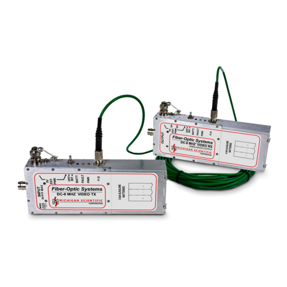
- Page 1 Fiber-Optic Systems User Manual Model: FO-HBAVT & FO-HBAVR EM Hardened Analog Video Link...
- Page 2 1 GHz to 2.5 GHz. 2. Setup Either the FO-HBAVT or FO-HBAVR may be connected to the DUT to measure or source a signal. Connect the FO-HBAVT to FO-HBAVR with ST multimode fiber-optic cables. The module connected to the DUT must be battery powered. The remote module may be powered by batteries or the external power adapter.
- Page 3 WARNING: The FO-HBAVR can only source impedance of 75 Ω. Improper termination will change the full-scale output signal levels. Set the input termination on the FO-HBAVT as shown in Figure 4. Figure 4: FO-HBAVT input termination switch Note: Use the 2 kΩ setting when external termination is used.
- Page 4 3. Operation The FO-HBAVT and FO-HBAVR were designed for use with alkaline batteries. The red BATT! indicator illuminates when the alkaline batteries need replacement. NiMH may be used but the low-battery indicator will not work as intended. To power the unit select INT.•...
- Page 5 3.2. FO-HBAVR Figure 6: FO-HBAVR point out To adjust the gain (G•) and offset (O•) potentiometers, carefully insert the provided flat head screw driver and turn. Offset and gain are set by following the User Adjustment Procedure found on the next page. The yellow FAULT indicator will trigger if there is no fiber-optic cable connected or the fiber-optic cable is causing too much optical loss.
- Page 6 Note: Perform a user adjustment at the start of each testing day and when the FO-HBST input termination is changed. Turn on both the FO-HBAVT and FO-HBAVR and allow for 5 min to warm-up Connect a digital volt meter (DVM) to the FO-HBAVR output...
- Page 7 6. Specifications Transmitter (FO-HBST) Voltage range ±1 V (75 Ω doubly terminated) Impedance 75 Ω / 100 Ω / 2 kΩ Over-voltage protection ±6 V continuous Resolution 4 mV Battery life 14 h Receiver (FO-HBSR) Noise 10 mV RMS Impedance 75 Ω...
Need help?
Do you have a question about the FO-HBAVT and is the answer not in the manual?
Questions and answers