Table of Contents
Advertisement
Quick Links
Vari KNX GPS
GPS Receiver
Technical specifications and installation instructions
Item number 70387
EN
Elsner Elektronik GmbH Control and Automation Engineering
Sohlengrund 16
75395 Ostelsheim
Germany
Phone +49 (0) 70 33 / 30 945-0
Fax
+49 (0) 70 33 / 30 945-20 www.elsner-elektronik.de
info@elsner-elektronik.de
Advertisement
Table of Contents

Summary of Contents for elsner elektronik Vari KNX GPS
- Page 1 Vari KNX GPS GPS Receiver Technical specifications and installation instructions Item number 70387 Elsner Elektronik GmbH Control and Automation Engineering Sohlengrund 16 75395 Ostelsheim Phone +49 (0) 70 33 / 30 945-0 info@elsner-elektronik.de Germany +49 (0) 70 33 / 30 945-20 www.elsner-elektronik.de...
-
Page 2: Scope Of Delivery
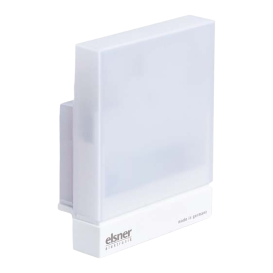
Description Description The GPS Receiver Vari KNX GPS for the KNX building system receives the GPS sig- nal for time and location and uses it to compute the position of the sun (azimuth and elevation). The compact housing of the Vari KNX GPS accommodates the receiver, evaluation circuits and bus-coupling electronics. -
Page 3: Installation And Start-Up
Elsner Elektronik is not liable for any changes in norms and standards which may occur after publication of these operating instructions. 2.2. Installation location The GPS Receiver Vari KNX GPS must be installed outside. GPS Receiver Vari KNX GPS • Status: 14.04.2016 • Errors excepted. Subject to technical changes. - Page 4 Magnetic fields, transmitters and interference fields from electrical consumers (e.g. flu- orescent lamps, neon signs, switch mode power supplies etc.) can block or interfere with the reception of the GPS signal. GPS Receiver Vari KNX GPS • Status: 14.04.2016 • Errors excepted. Subject to technical changes.
-
Page 5: Device Design
2.4.1. Preparation for installation Fig. 4 The cover and lower part of the housing are connected together. Pull both parts apart in a straight line. GPS Receiver Vari KNX GPS • Status: 14.04.2016 • Errors excepted. Subject to technical changes. -
Page 6: Fitting The Lower Part Of The Housing With Mounting
If the power lead is to be surface-mount- ed, the cable guide is broken off. The lead is then fed into the device from the bot- tom of the housing. Cable guide GPS Receiver Vari KNX GPS • Status: 14.04.2016 • Errors excepted. Subject to technical changes. - Page 7 The device is installed on the pole with the enclosed stainless steel mounting band. Fig. 9 Feed the mounting band through the eyelets in the lower part of the housing. GPS Receiver Vari KNX GPS • Status: 14.04.2016 • Errors excepted. Subject to technical changes.
-
Page 8: Completing The Installation
The device is delivered ex works with the bus address 15.15.250. You can program a different address in the ETS by overwriting the address 15.15.250 or by teaching the device via the programming button. GPS Receiver Vari KNX GPS • Status: 14.04.2016 • Errors excepted. Subject to technical changes. -
Page 9: Maintenance
If there is major soiling, the function of the receiver may be limited. ATTENTION The device may be damaged if water penetrates the housing. • Do not clean with high pressure cleaners or steam jets. GPS Receiver Vari KNX GPS • Status: 14.04.2016 • Errors excepted. Subject to technical changes.
Need help?
Do you have a question about the Vari KNX GPS and is the answer not in the manual?
Questions and answers