Table of Contents
Advertisement
Safety • Assembly • Operation • Adjustments • Maintenance • Troubleshooting • Parts Lists • Warranty
OPERATOR'S MANUAL
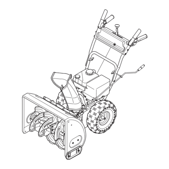
Two-Stage Snow Thrower
IMPORTANT:
READ SAFETY RULES AND INSTRUCTIONS
CAREFULLY BEFORE OPERATING EQUIPMENT.
769-04119A
PRINTED IN U.S.A.
MTD Products Ltd., P. O. Box 1386, KITCHENER, ONTARIO N2G 4J1
7/20/09
Advertisement
Table of Contents

Related Manuals for MTD Pro 31AM63FE529

Summary of Contents for MTD Pro 31AM63FE529
- Page 1 Safety • Assembly • Operation • Adjustments • Maintenance • Troubleshooting • Parts Lists • Warranty OPERATOR’S MANUAL Two-Stage Snow Thrower IMPORTANT: READ SAFETY RULES AND INSTRUCTIONS CAREFULLY BEFORE OPERATING EQUIPMENT. 769-04119A PRINTED IN U.S.A. MTD Products Ltd., P. O. Box 1386, KITCHENER, ONTARIO N2G 4J1 7/20/09...
-
Page 2: Table Of Contents
This Operator’s Manual is an important part of your new snow thrower. It will help you assemble, prepare and maintain the unit for best performance. Please read and understand what it says. Table of Contents Safety Labels ............3 Maintaining Your Snow Thrower ...... 14 Safe Operation Practices ........ -
Page 3: Safety Labels
This page depicts and describes safety symbols that may appear on this product. Read, understand, and follow all instructions on the machine before attempting to assemble and operate. Symbol Description Safety READ THE OPERATOR’S MANUAL(S) Read, understand, and follow all instructions in the manual(s) before Symbols attempting to assemble and operate. -
Page 4: Safe Operation Practices
WARNING: Engine Exhaust, some of its constituents, and certain vehicle compo- nents contain or emit chemicals known to State of California to cause cancer and birth defects or other reproductive harm. DANGER: This machine was built to be operated according to the safe operation practices in this manual. - Page 5 8. Exercise extreme caution when operating on or crossing gravel 3. Check bolts and screws for proper tightness at frequent surfaces. Stay alert for hidden hazards or traffic. intervals to keep the machine in safe working condition. Also, visually inspect machine for any damage. 9.
-
Page 6: Setting Up Your Snow Thrower
Setting Up Your Snow Thrower Figure 3-2 NOTE: References to right or left side of the Figure 3-1 snow thrower are deter- 1. Observe the lower rear area of the snow thrower to mined from behind the be sure both cables are aligned with roller guides. unit in the operating Pull up and back on the upper handle, align the upper handle with the lower handle. - Page 7 Clean-Out Tool Setting Up Your Snow Thrower Figure 3-6 Figure 3-5 Clean-Out Tool Never use your hands WARNING: Never use your hands to to clean snow and clear a clogged chute assembly. Shut ice from the chute off engine and remain behind handles until all moving parts have stopped assembly or auger before unclogging.
-
Page 8: Operating Your Snow Thrower
Know Your Snow Thrower Drive Control Shift Lever Operating Auger Control Headlight Your Snow (optional) Shift Lever (optional) Thrower Chute Directional Control Chute Assembly Clean-Out Engine Controls Tool Muffler Oil Filler Cap/Dipstick WARNING Primer Fuel Fill Cap Ignition Key Read, understand, Throttle Choke and follow all instruc-... - Page 9 Auger Control Chute Assembly The distance snow is thrown can be adjusted by AUGER changing the angle of the chute assembly. See “Making CONTROL Adjustment” Section. Chute Clean-Out Tool The clean-out tool is conveniently fastened to the rear of the auger housing with a mounting clip. Operating 1.
- Page 10 Gas & Oil Fill-Up Determine that your home’s wiring is a three-wire grounded system. Ask a licensed electrician if you Service the engine with gasoline and oil as instructed in are unsure. If you have a grounded three-prong the separate engine manual packed with your unit. Read receptacle, proceed as follows.
- Page 11 To Engage Drive 1. With the engine running near top speed, move shift lever to one of six FORWARD positions or two REVERSE positions. Select a speed appropriate for the snow conditions that exist. Do not shift speeds while the drive is engaged. 2.
-
Page 12: Makingadjustments
Auger Control Refer to Auger Control Test on Page 11 to adjust the auger control. Shift Cable If the full range of speeds (forward and reverse) cannot be achieved, refer to the figures to the right and adjust Making the shift cable as follows: 1. - Page 13 Making Adjustments Figure 5-6 - Standard Skid Shoe Figure 5-7 - Steel Reversible Figure 5-8 - Plastic Reversible Skid Shoes The space between the skid shoes and the ground can be adjusted. • For close snow removal on a smooth surface, raise skid shoes higher on the auger housing.
-
Page 14: Maintaining Your Snow Thrower
Engine Refer to the separate engine manual packed with your unit for all engine maintenance. Lubrication Engine Refer to the separate engine manual packed with your Maintaining unit for all engine lubrication instructions. Your Snow Gear Shaft The gear (hex) shaft should be lubricated at least once Thrower a season or after every 25 hours of operation. - Page 15 Auger Belt Replacement 2. Carefully pivot the snow thrower up and forward so that it rests on the auger housing. Remove the frame WARNING: Run the engine com- cover from the underside of the snow thrower by pletely dry of gasoline before tipping removing self-tapping screws which secure it.
- Page 16 Drive Belt Replacement WARNING: Run the engine com- pletely dry of gasoline before tipping snowthrower. To remove and replace your snow thrower’s auger belt, proceed as follows: Maintaining 1. Remove the plastic belt cover on the front of the engine by removing the two self-tapping screws. See Your Snow Figure 6-4.
-
Page 17: Off-Season Storage
NOTE: If you’re replacing the friction wheel assembly as a whole, discard the worn part and slide the new part onto the hex shaft. Follow the steps above in reverse order to reassemble components. If you’re disassem- bling the friction wheel and replacing only the rubber ring, proceed as follows: Maintaining 6. -
Page 18: Trouble Shooting
Problem Cause Remedy Engine fails to start 1. Choke not in ON position. 1. Move choke to ON position. 2. Spark plug wire disconnected. 2. Connect wire to spark plug. 3. Fuel tank empty or stale fuel. 3. Fill tank with clean, fresh gasoline. 4. -
Page 19: Warranty
4 YEAR LIMITED WARRANTY For FOUR YEARS from the date of retail purchase within Canada, MTD PRODUCTS LIMITED will, at its option, repair or replace, for the original purchaser, free of charge, any part or parts found to be defective in material or workmanship. This warranty does not cover: Warranty 1. - Page 20 NOTES: For parts and/or accessories refer to customer support on page 2. Adressez-vous au «Service après-vente» à la page 2 pour ce qui concerne les pièces et/ou accessoires.
-
Page 21: Illustrated Parts Lists
Model Wheel Ass'y De scrip tion Tire Axle Spacer Modèle En sem ble de De scrip tion Roue Jante Essieu Entretoise roue 31AH54LF 634-04145 16 x 4.8 x 8 LH X-Trac 734-2038 634-04173 738-04180 731-04873 31AH54LS 634-04146 16 x 4.8 x 8 RH X-Trac 734-2038 634-04173 31AH54K3... - Page 23 PART N° DE N° DE RÉF PIÈCE DE SCRIP TION DE SCRIP TION 631-04133A LH Clutch Lock Han dle Ass’y Poignée d’embrayage CG 631-04134B RH Clutch Lock Han dle Ass’y Poignée d’embrayage CD 684-04105B En gage ment Han dle As sem bly LH Poignée d’entraînement CG Parts List 684-04106B...
- Page 24 24 30...
- Page 25 PART N° DE N° DE RÉF PIÈCE DE SCRIP TION DE SCRIP TION 656-04025A Fric tion Wheel Disc As sem bly Disque de roue de fric tion 684-04153 Fric tion Wheel Ass’y, Bear ing 5.5 OD Roue du fric tion, roulement 5,5 DE 684-04154 Fric tion Wheel Sup port Brkt Ass’y Sup port de la roue de fric tion...
- Page 26 NOTE: Housing may not be exactly as shown. REMARQUE : L'habitacle peut être légèrement différent. 30 in/po...
- Page 27 PART N° DE N° DE RÉF PIÈCE DE SCRIP TION DE SCRIP TION 731-2643 Clean-Out Tool Outil de dégagement de la goulotte 684-04057A Im pel ler Ass'y 12 po Ventilateur 710-0347 Hex Screw 3/8-16 x 1.75 Vis à tête hex 3/8-16 x 1,75 710-0451 Car riage Bolt 5/16-18 x .75 Boulon ordi naire 5/16-18 x 0,75...
- Page 28 Manual Chute Control with two piece chute crank/ Commande de la goulotte manuelle avec manivelle de la goulotte supérieure et inférieure. Manual Chute Control with one piece chute crank/ Commande de la goulotte manuelle avec manivelle de la goulotte.
- Page 29 PART N° DE N° DE RÉF PIÈCE DE SCRIP TION DE SCRIP TION 712-04063 Flange Locknut 5/16-18 Gr. F Ny lon Contre-écrou à embase 5/16-18 Qual. F ny lon 731-04354B Up per Chute Goulotte supérieur 720-0284 Han dle Knob As sem bly Bou ton 710-0451 Car riage Bolt 5/16-18 x .75...
Need help?
Do you have a question about the 31AM63FE529 and is the answer not in the manual?
Questions and answers