
Related Manuals for Tavish Design 6SL7

Summary of Contents for Tavish Design 6SL7
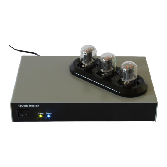
- Page 1 Vintage 6SL7 Phono Stage (MM / MC) Assembly and Setup Manual , LLC AVISH ESIGN Made in U.S.A.
-
Page 2: Table Of Contents
ABLE OF ONTENTS 1. Introduction & Quick Start 2. Safety Considerations 3. Assembly 4. Setup & Operation 4.1. Initial Setup 4.2. Operation 4.3. Tube Replacement 5. Technical Information 5.1. Specifications 5.2. Schematics 5.3. Parts Placement Diagram 5.4. Parts Lists 6. Warranty and Service 7. -
Page 3: Introduction & Quick Start
Vacuum tubes present some unique safety considerations, so please take time to look over the safety considerations in Section 2. Kit assembly instructions begin in Section 3. If you purchased the Vintage 6SL7 Phono Stage as an assembled unit, please see the Quick Start instructions below. -
Page 4: Safety Considerations
Lethal voltages can remain in the electronics after the unit is unplugged. Refer servicing to Tavish Design, LLC. If the unit must be opened for servicing, unplug it and wait at least 10 minutes for internal capacitors to discharge. -
Page 5: Assembly
Please read through these instructions before beginning assembly. If you are in doubt about your ability to safely and successfully assemble the kit, please send it back, or first get some experience with other electronics kits. No liability is assumed by Tavish Design, LLC. The ARRL Handbook for Radio Amateurs has a useful chapter on electrical safety. - Page 6 Step-by-step Instructions: 1. The surface mount JFETs are supplied pre-installed with the complete kit. If you purchased the blank PCB, install the JFETs first. The 2SK209 are marked “XL” and the MMBFJ270 are marked “61S”. Melt a small amount of solder on one of the pads. Then, holding the FET with a pair of tweezers, re-melt the solder and place one leg of the JFET in the molten solder.
- Page 7 Photo 3.2: PCB after step 3. 4. Install Q2 and IC2-IC3 using a 3/8” #4-40 screw, flat washer, split washer, and nut to mount Q2 and IC2 (no flat washer needed for IC2) to the PCB before soldering. IC3 slides into heatsink HS1 and mounts upright.
- Page 8 Photo 3.3: PCB after step 9. 10. Install trimmers R9 (500 Ω) and R23 (10 kΩ). 11. Install DIP sockets, noting that they have a polarity as marked on the PCB. 12. Install RLY1-RLY2, noting that they have a polarity as marked on the PCB. 13.
- Page 9 Photo 3.4: PCB after step 14. 15. Install J1-J3, SW1, and U1. For J1-J2, remove the chrome cover to expose the black insulator underneath before installing. This prevents the signal ground from shorting to the chassis (they must be isolated to prevent ground loops). See photo 3.5 below. Solder only one leg of each component, making sure they are seated against the PCB, then test fit the PCB in the enclosure.
- Page 10 16. Prepare a 22ga. wire 2¾” (7 cm) long to connect the PCB wirepad CHASSIS to the rear panel ground post, using the ¼-20 ground terminal. Prepare a 22 ga. twisted pair 5½” (14 cm) long to connect the wirepads PS1 and PS2 to the front panel rocker switch, using 0.187” quick connect terminals.
- Page 11 possible and twisted as tightly as possible. Bend the ground lug toward body of the connector as shown in the assembly detail in photo 3.7. Photo 3.7: Connector wiring assembly detail. 25. In a similar manner, install and wire the red RCA jack in the upper chassis hole for the moving coil input (red to the center signal terminal).
- Page 12 Photo 3.8: Completed phono stage after step 29. 30. Install the tubes (see section 4.1 below). Connect the negative lead of your voltmeter to the black PCB test point installed at the AGND pad. Connect the positive lead of your voltmeter to the P18 pad using the yellow PCB test point installed there.
-
Page 13: Setup & Operation
ETUP 4.1 I NITIAL ETUP Setup consists of installing the tubes (if needed), selecting the Moving Magnet (MM) or Moving Coil (MC) input, and setting the cartridge loading and MC gain (if needed). The factory settings for these should work well with most MM cartridges, and with low-output MC cartridges, so you might not need to adjust anything. - Page 14 Cartridge Loading and Moving Coil Gain Cartridge loading and the MC gain setting are set with internal DIP switches. The factory settings for these should work well with most MM cartridges, and with low-output MC cartridges. To select other settings, unplug the unit and wait 10 minutes for the internal capacitors to discharge. Remove the cover by removing 4 screws.
- Page 15 MM Load Setting (S2) S2 Positions (1 – 7) OFF = 0, ON = 1 No added capacitance 0001000 47 pF 1001100 Factory Default 100 pF 0101010 147 pF 1101110 180 pF 0011001 227 pF 1011101 280 pF 0111011 327 pF 1111111 Table 4.2: MM Load Settings.
-
Page 16: Operation
Replace tubes with the same type: only 6SL7GT tubes can be used in the phono stage. In particular, many people confuse the 6SL7 with the 6SN7. Unfortunately, the 6SN7 cannot be used in any position in the phono stage. -
Page 17: Technical Information
ECHNICAL NFORMATION Parameter Specification Gain 41 dB Moving Magnet 53 dB High-Output Moving Coil 61 dB Low-Output Moving Coil RIAA Equalization Accuracy ±0.5 dB, 25 Hz – 20 kHz Signal-to-noise ratio >79 dBA ref. 5 mV @ 1kHz, Moving Magnet (A-weighted) >79 dBA ref. - Page 18 Measured RIAA Equalization Accuracy R1(ST) L1(ST) -0.2 R2(TS) -0.4 L2(TS) -0.6 -0.8 1000 10000 Frequency, Hz Fig. 5.1: Typical measured RIAA equalization error with both Sovtek 6H9C/6SL7GT (ST) and Tung Sol Reissue 6SL7GT (TS) tubes, left and right channels. Error is <0.5 dB from 25 Hz – 20 kHz for all curves. Measured THD vs.
- Page 19 Fig. 5.3: Schematic, sheet 1 of 4...
- Page 20 Fig. 5.4: Schematic, sheet 2 of 4...
- Page 21 Fig. 5.5: Schematic, sheet 3 of 4...
- Page 22 Fig. 5.6: Schematic, sheet 4 of 4...
- Page 23 Fig. 5.7: Circuit board component placement.
- Page 24 Qty Part Value Description Vendor Manufacturer or Vendor Number(s) Part No. 1 C1 1000uF electrolytic 5mm LS Digikey 493-1790-ND 4 C2, C12, 2200uF audio grade Mouser 647-UKA0J222MPD C103, C203 6.3v electrolytic 5mm LS 1 C3 2200uF audio grade Mouser 647-UKA1C222MHD electrolytic 5mm LS 1 C4 100uF 16v...
- Page 25 Qty Part Value Description Vendor Manufacturer or Number(s) Vendor Part No. 1 B1 2A 100v bridge rectifier Mouser 621-KBP201G 1 D1 1N4744 15v 1W Zener diode 4 D2, D4, D6 1N4002 1A 100v rectifier diode 1 D3 1N5817 1A 20v Schottky 1 D5 1N5817 1A 20v Schottky...
- Page 26 Part Value Description Vendor Vendor Part No. Number(s) R1, R8, R14, 0 = jumper jumper R31, R32 5 R3, R116, 330 1/2W 1% (or metal film Mouser 273-330-RC R121, R216, 332) R221 7 R4, R111, 1k 1/2W 1% metal film Mouser 273-1K-RC R122, R125, R211, R222,...
- Page 27 2 R103, R203 3.3k 1W 5% metal oxide Digikey 3.3KW-1-ND 2 R104, R204 49.9k 1/2W 1% metal film Mouser 273-49.9K-RC 2 R105, R205 82k 1/2W 1% metal film Mouser 273-82K-RC 2 R106, R206 10k 1/2W 1% metal film Mouser 273-10K-RC 2 R107, R207 470k 1/2W 1% metal film...
- Page 28 Qty Part Value Description Vendor Vendor Part No. Number(s) 2 RLY1, G6K-2P-DC5 Omron low-signal relay Mouser 653-G6K-2P-DC5 RLY2 2 S1, S2 7 position DIP C&K DIP switch, gold Mouser 611-SDA07H1BD switch plated contacts 1 S3 2 position DIP C&K DIP switch, gold Mouser 611-SDA02H1BD switch...
- Page 29 Qty Description Vendor Manufacturer or Vendor Part No. 1 Dialight green hi-efficiency 3mm panel mount LED Mouser 645-558-0501- 023F 1 Dialight blue hi-efficiency 3mm panel mount LED Mouser 645-558-6003- 027F 1 rocker switch (R13-73A2-B-02-R) Jameco 316111 2 Quick connect terminals, 0.187” Digikey A27804-ND 8 1/4"...
-
Page 30: Warranty And Service
(6) years from the date of purchase (6 months on tubes). If you discover a defect, Tavish Design will (at its option) repair or replace the product at no cost to you (excluding return shipping and handling outside the 48 continental United States) provided that you send it prepaid to Tavish Design (see Section 6.2). -
Page 31: Do-It-Yourself Guidance (Faq)
(RMA) number, along with packing and shipping instructions and a street address for delivery. For kits, Tavish Design offers a repair service in the event you are unable to get your kit working. Please contact us for more details. - Page 32 option is to use an external 18 VAC transformer in its own enclosure. One DIYer reported success with the Amveco / Talema 70061. Whatever you use, make sure it provides at least 18.0 VAC under 1A load; some nominal 18v transformers don’t provide 18v under load. If you do use a standard 18 VAC transformer instead of a wall transformer, resist the temptation to mount it in the same enclosure as the phono stage board.
-
Page 33: Design Changes With Release
ESIGN HANGES ELEASE 1. New components D5 and C11 are added to prevent turn-off thump in MC mode. Previous Design Changes with Release 2.1: 1. R110 and R210 become 160kΩ for Tung Sol and JJ 6SL7GT (but remain 150kΩ for Sovtek 6H9C). 2. -
Page 34: Copyright, Trademark, And Disclaimers
RADEMARK ISCLAIMERS © Copyright Tavish Design, LLC 2018. All rights reserved. No part of this document may be reproduced by any means or translated to other languages without prior written consent of Tavish Design, LLC. Tavish Design® is a registered trademark of Tavish Design, LLC.
Need help?
Do you have a question about the 6SL7 and is the answer not in the manual?
Questions and answers