Table of Contents
Advertisement
Advertisement
Table of Contents

Related Manuals for EBIKELING NC-81F

Summary of Contents for EBIKELING NC-81F
- Page 1 Electric Bike Display NC-81F USER MANUAL...
-
Page 2: Table Of Contents
TABLE OF CONTENTS Product Name and Model Number Spesifications Appearance and Size Function Overview and Functional Areas 4.1 Functional Overview 4.2 Functional Areas 4.3 Button Definitons Routine Operations 5.1 Power On/Off 5.2 Display Interface Switching 5.3 Walk Boost Mode and Cruise Enable Setting 5.4 Turning On/Off Lights 5.5 PAS Level Selection 5.6 Battery Level Display... - Page 3 TABLE OF CONTENTS 6.9 Start-Up Setting 6.10 Drive Mode Setting 6.11 Pedal Assist Sensitivity Setting 6.12 Pedal Assist Strength Setting 6.13 Number of Pedal Assist Sensor Magnets Setting 6.14 Controller Current Limit Setting 6.15 ODO Resets Setting 6.16 Power On Password Setting Shortcut Operation Quality Assurance and Warranty 8.1 Warranty Info...
-
Page 4: Product Name And Model Number
Product Name and Model Number Smart LCD display for electric bicycle; Model: NC-81F. Specification 36V/48V/52V power supply Supplied current to the controller 50mA Display rated current 15mA Operating temperature -20 ~ 60 °C Display maximum current 30mA Storage temperature -30 to 70°C Shutdown leakage current <1uA... -
Page 5: Function Overview And Functional Areas
Front View Dimensions Side View Dimensions Function Overview and Functional Areas 4.1 Functional Overview The NC-81F display offers a variety of features to suit your riding needs, including: Battery level indicator Error code indicator Pedal assist (PAS) level indicator Cruise control indicator (optional) -
Page 6: Functional Areas
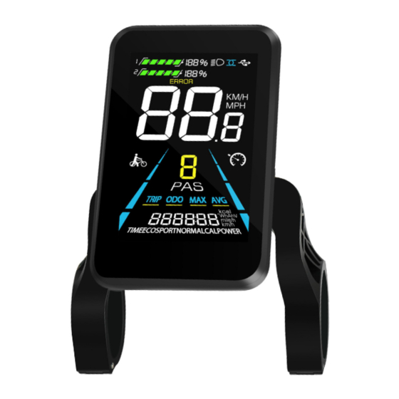
KM/H Current Speed Cruise Walk Boost PAS Level Trip Odometer Odemeter MAx Speed Value and Unit Average Speed 4.3 Button Definitions The NC-81F display is equipped with five buttons on the corresponding operating unit: Power On/Off Plus Minus Light Toggle... -
Page 7: Routine Operations
Routine Operations 5.1 Power On/Off Long press to power on/off the display. When the display is off, it will not use the battery power and the leakage current is less than 1uA. The display will automatically shut off if it is not used for more than 10 minutes. 5.2 Display Interface Switching When the display is powered on, it will show the Current Speed (km/h) and Trip Odometer (km) by de- fault. -
Page 8: Walk Boost Mode And Cruise Enable Setting
5.3 Walk Boost Mode and Cruise Enable Setting The whole bicycle is at stable speed, Long Long Press and hold , the electric bicycle press and the bicycle will enter the enters the walk boost mode. The electric cruise state. The bicycle runs at a constant bicycle will walk at a fixed speed of 6 km per speed at the speed you control and screen hour and the display shows... -
Page 9: Pas Level Selection
5.5 PAS Level Selection Press to switch PAS level of electric bicycle, thus changing the motor output power. PAS level display interface... -
Page 10: Battery Level Display
5.6 Battery Level Display Full Power Two Bars Power The Battery level is shown as 5 bars. When the battery is full charged, all of the 5 bars lighten up. When the battery is fully depleted, the bar Four Bars Power One Bar Power will begin to flash, warning the user to charge the battery as soon as possible. -
Page 11: Personalized Parameter Settings
Personalized Parameter Settings Each setting needs to be done with the bicycle stationary. Please also note that the following operations can only be performed within 8 seconds before starting the machine. The personalized parameter setting procedure is as follows: When the display is ON and the speed shows 0, Press and hold simultaneously for more Press... -
Page 12: Metric And Imperial Setting
6.2 Metric and Imperial Setting 02P is the metric and imperial setting, 00 for metric and 01 for imperial. Press to enter the parameter changing state. Press the to select the parameter and press to save theparameter setting and return to the personalized parameter setting interface. -
Page 13: Pas Level Setting
6.5 PAS Level Setting 05P is the Pedal assist level setting. The available PAS level settings are: 0~3, 0~5, 0~9. Press to enter the parameter changing state. Press the to select the parameter and press to save theparameter setting and return to the personalized parameter setting interface. -
Page 14: Speed Limit Setting
6.8 Speed Limit Setting 08P is the speed limit setting. The adjustable speed limit range is: 1~100km/h. (The maximum adjustable speed limit varies by different protocols). Press to enter the parameter changing state. Press the to select the parameter and press to save theparameter setting and return to the personalized parameter setting interface. -
Page 15: Pedal Assist Sensitivity Setting
6.11 Pedal Assist Sensitivity Setting 11P is the pedal assist sensitivity setting. When set to higher numbers, it will take more crank rotations to activate the motor. On lower numbers, it will take little crank rotation to activate the motor. The adjustable range is: 1~24. -
Page 16: Controller Current Limit Setting
6.14 Controller Current Limit Setting 14P is the controller current limit setting. The adjustable range is: 1~50A. Press to enter the parameter changing state. Press the to select the parameter and press to save theparameter setting and return to the personalized parameter setting interface. -
Page 17: Shortcut Operation
Power-on Password OFF Power-on Password Power-on password setting interface Activated interface interface In the password setting mode, the adjustable digit will flash. Press the to select the parameter and press to save the numbers and go to the next digit setting. Long press save the parameter setting and return to the personalized parameter setting interface after finish setting the four digits in turn. -
Page 18: Quality Assurance And Warranty
7.2 Trip odometer reset operation The display can record trip odometer and odometer. Trip odometer is not automatically reset after turning off. The trip odometer needs to be reset manually. Enter into the main setting interface and keep the speed at 0, press and hold simultaneously for 2s to reset the trip odometer. -
Page 19: Precautions
Standard Wire Sequence Standard wire color Function Red (VCC) Display power wire Blue (Kp) Controller power wire Black (GND) Display ground wire Green (RX) Display data reception wire Yellow (TX) Display data transmit wire Some models are equipped with waterproof connectors and the color inside wires can not be seen. Precautions Pay attention to all the general operating when using the products and do not plug and unplug the display while it is powered on.
Need help?
Do you have a question about the NC-81F and is the answer not in the manual?
Questions and answers
went through the parameters and wont show speed when throttle spins wheel
If the EBIKELING NC-81F does not show speed when the throttle spins the wheel, a possible issue could be a speed sensor malfunction or incorrect speed sensor magnet number setting (07P). Another possibility is a communication issue or motor-related error, such as EE02 (communication failure) or EE06 (motor phase failure).
This answer is automatically generated
How to re set the password
To reset the password for the EBIKELING NC-81F, follow these steps:
1. Enter the power-on password setting (16P).
2. Press to enter the parameter changing state.
3. Select the parameter using the controls.
4. Set a new four-digit password.
5. Confirm the new password.
Note: The factory default password is 1212. Ensure you remember the new password, as forgetting it will prevent display access.
This answer is automatically generated
What does error 30 mean
Bonjour, Comment procéder pour sortir de 16p si on a perdu le code? (Le 1212,1234 ,ne fonctionne pas)
Do u no the code to 16p settings plz
The 16P setting for the EBIKELING NC-81F is the power-on password setting. The factory default password is 1212, and users can activate or deactivate it using the following codes:
- PSd-y: Power-on password is activated.
- PSd-n: Power-on password is off.
Users can also set a custom four-digit password.
This answer is automatically generated