Advertisement
Quick Links
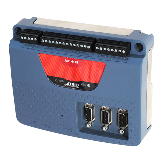
CAN PORT FOR TRIO CAN
I/O, DEVICENET SLAVE,
CANOPEN OR USER
PROGRAMMABLE
PANEL MOUNT OR DIN
RAIL MOUNT
STATUS LEDS
MOTION COORDINATOR
MOTION COORDINATOR
Quick Connection Guide
(Please refer to the Motion Coordinator Technical Reference Manual for Full Details)
2 ANALOGUE INPUTS AND
2 VOLTAGE OUTPUT AND
8 DIGITAL INPUTS
INCLUDING
6 X REGISTRATION INPUTS
AND 4 BI-DIRECTIONAL I/O
RS232 / RS 485
MODBUS-RTU,
HOSTLINK OR USER
PROGRAMMABLE
MC403 / MC403-Z
WDOG RELAY
3 ENCODER CONNECTIONS
(6MHZ) OR DRIVE AS
STEPPER OUTPUTS
(2MHZ)
MICRO SD CARD
ETHERNET
PROGRAMMING, MODBUS-
TCP, ETHERNET IP
Advertisement

Related Manuals for Trio MC403


Summary of Contents for Trio MC403
- Page 1 2 ANALOGUE INPUTS AND 2 VOLTAGE OUTPUT AND WDOG RELAY 8 DIGITAL INPUTS INCLUDING 6 X REGISTRATION INPUTS AND 4 BI-DIRECTIONAL I/O CAN PORT FOR TRIO CAN I/O, DEVICENET SLAVE, CANOPEN OR USER 3 ENCODER CONNECTIONS PROGRAMMABLE (6MHZ) OR DRIVE AS STEPPER OUTPUTS...
- Page 2 This is a 5 way 3.5mm pitch connector. The 5-WAY connector is used both to provide the 24 CONNECTOR Volt power to the MC403(-Z) and provide connections for I/O expansion via Trio’s CAN MC 403 I/O expanders. A 24V dc, Class 2 transformer or power source must be provided as this powers the unit.
-
Page 3: Serial Connections
SERIAL Serial Connector CONNECTIONS Function Note RS485 Data In A Rx+ MC 403 Serial Port #2 RS485 Data In B Rx- RS232 Transmit Serial Port #1 0V Serial RS232 Receive Serial Port #1 RS485 Data Out Z Tx- Serial Port #2 RS485 Data Out Y Tx+ I/O CONNECTOR 1 Input 5... - Page 4 WDOG MC 403 WDOG Analogue 0V WDOG / Analogue Inputs / Outputs I/O 24V must be applied to power the voltage outputs. (MC403 ONLY) ANALOGUE INPUT S ANALOGUE OUTPUTS AIN0: 0 TO 10V AOUT 0 TO AOUT 1 AIN1: 0 TO 10V Output: +/-10V at 5mA Output impedance: 100 Ohms.
- Page 5 WDOG=OFF command. ALL STEPPER AND SERVO AMPLIFIERS MUST BE INHIBITED WHEN THE AMPLIFIER ENABLE OUTPUT IS OPEN CIRCUIT To other axis enables Amplifi er 24V 0V Enable 1 Amplifi er Enable Enable 2 VIN + VIN- Trio Controller Servo Amplifi er...
- Page 6 STEPPER STEP 5 4 3 2 1 OUTPUTS / ENCODER INPUTS 9 8 7 6 MC 403 DIRECTION 5 4 3 2 1 9 8 7 6 5 4 3 2 1 BENABLE 9 8 7 6 Current Limit Servo Axis Stepper Axis Absolute Encoder Enc.
-
Page 7: Grounding And Shielding
Power 24V+ CANbus (H) Ensure that: SHEILD 1. The shield screw is grounded CANbus (L) as close to the MC403(-Z) as possible. 24V Return (-) 2. 0V, V- and E- connections are SERVO DRIVE NOT used for terminating I/O CONNECTOR 3 screens. -
Page 8: Status Leds
In addition, bond together the 0V (24V return) terminals of all system components so as to minimise current fl owing in the serial cables. Serial cable RS232 Serial cable RS485 Trio Motion Technology Ltd. Trio Motion Technology LLC Trio Shanghai Trio India Website: www.triomotion.com...