
Related Manuals for ZANTIA NARA PLUS 24

Summary of Contents for ZANTIA NARA PLUS 24
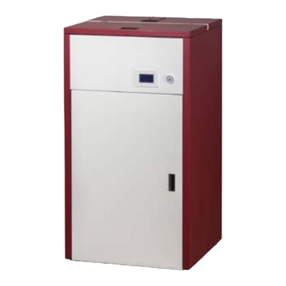
- Page 1 NARA PLUS 24 NARA PLUS 34 CALDEIRAS PELLET PELLET BOILERS Manual de uso e manutenção PT - Use and maintenance manual EN -...
-
Page 3: Table Of Contents
Índice SUMÁRIO 1 INTRODUÇÃO ..............................6 1.1 REVISÕES DA PUBLICAÇÃO ............................6 1.2 COMO CONSERVAR E COMO CONSULTAR O MANUAL ...................6 1.3 SIMBOLOGIA ................................6 1.4 ADVERTÊNCIAS PARA A SEGURANÇA ........................6 1.5 CONDIÇÕES DE GARANTIA ............................8 1.5.1 ADVERTÊNCIAS - NOTAS PARA O CLIENTE ...........................8 1.6 PEDIDO DE PEÇAS SOBRESSALENTES ........................8 1.7 ELIMINAÇÃO ................................8 1.8 USOS PERMITIDOS E PROIBIDOS ..........................9... - Page 4 Índice 4.2.3.3 CALIBRAÇÃO DA VENTOINHA DE COMBURENTE ......................21 4.2.4 MENU DE GESTÃO DE AQUECIMENTO............................21 4.2.4.1 TERMÓSTATO CALDEIRA ................................ 21 4.2.4.2 VERÃO - INVERNO ..................................21 4.2.5 MENU CRONO ....................................22 4.2.5.1 MODALIDADE .................................... 22 4.2.5.2 PROGRAMA ....................................22 4.2.6 MENU CARREGAMENTO MANUAL / CARGA INICIAL ......................
- Page 5 7 PROBLEMA/CAUSA/SOLUÇÃO ........................31 8 DATI TECNICI E DIMENSIONI - TECHNICAL DATA AND DIMENSIONS- DONNÉES TECHNIQUES ET DI- MENSIONS - DATOS TÉCNICOS Y DIMENSIONES - ..................65 8.1 NARA PLUS 24 ................................65 8.2 NARA PLUS 34 ................................65 Mod. NARA PL. 24-34 rev 01...
-
Page 6: Introdução
O conteúdo do presente manual é de natureza estritamente rial inflamável (por exemplo, madeira, alcatifa e plástico). técnica e de propriedade da ZANTIA Climatização S.A. • Para a utilização correta do produto e dos equipamentos eletrónicos conectados a ele e para prevenir incidentes, Nenhuma parte deste manual pode ser traduzida para outro devem ser sempre observadas as indicações referidas no... - Page 7 • não se responsabiliza por proble- ZANTIA Climatização S.A. tipo parquet ou alcatifa. (considerando que a placa deve mas, adulterações, roturas e outras ocorrências, provocados ter uma borda saliente na parte dianteira da caldeira de pela inobservância das indicações apresentadas no presente...
-
Page 8: Condições De Garantia
As intervenções, grandes ou pequenas, devem ser efetuadas e) deterioração causada por agentes físicos ou químicos; exclusivamente por pessoal técnico autorizado Zantia. Para f) transporte ou adulterações efetuadas por pessoal não au- eventuais solicitações de peças sobressalentes, procurar o torizado. -
Page 9: Usos Permitidos E Proibidos
Instalação 1.11 ACESSÓRIOS FORNECIDOS COM O PRODUTO lizados de modo eco-compatível. O produto pode ser entregue aos respetivos centros de recolha seletiva colocados à disposição O produto é fornecido com: pelas administrações municipais, ou então aos revendedores • Cabo de alimentação; que fornecem este serviço. -
Page 10: Procedimento De Abertura Da Embalagem
As informações indicadas acima são puramente indicativas para uma instalação correta; a ZANTIA não se responsabiliza pelo que diz Climatização S.A. respeito à instalação. -
Page 11: Terminal
Instalação a altura da cumeeira não deverão estar muito próximos do terminal (ver a fig.5). telhado plano telhado inclinado fig. 4 modalidades permitidas e proibidas de instalação de descarga de fumos fig. 5 modalidades permitidas e proibidas de instalação do terminal •... -
Page 12: Posicionamento
Instalação POSICIONAMENTO Zona de irradiação 2.5.1 NOTAS GERAIS É proibida a instalação do produto nos quartos de dormir, nas casas de banho e nos locais onde já existe um outro aparelho de aquecimento despro- vido de um fluxo de entrada de ar próprio e ade- quado (lareira, caldeira, etc.), em ambientes exter- nos expostos aos agentes atmosféricos ou em zonas húmidas. -
Page 13: Proteção Do Pavimento
Instalação Distância do sistema de descarga dos fumos de elementos 2.5.4 DISTÂNCIAS MÍNIMAS PARA O POSICIONA- inflamáveis MENTO DA TOMADA DE AR A tomada de ar comburente da caldeira a pellets não pode ser conectada a um sistema de distribuição de ar ou diretamente à... -
Page 14: Conduta Da Descarga De Fumos
Instalação Ref. Descrição Fluxo H2O radiadores ¾” Saída sanitários quente ½” Entrada H2O fria linha hídrica ½” Torneira carregamento Retorno H2O quente ACS radiadores ¾” Tubo descarga H2O válvula de segurança ½” Ligação sem kit sanitário Ref. Descrição fig. 10 pontos de conexão sem kit sanitário Caudal radiadores Retorno radiadores Ref. -
Page 15: Furos Para A Passagem Do Tubo De Des- Carga Na Parede Ou No Teto: Isolamentoe Diâmetro Aconselhados
Instalação mm. O diâmetro dos tubos depende do tipo do sistema. varia de acordo com o tipo de instalação (ou seja, segundo o diâmetro do tubo de evacuação) e com o tipo de parede ou COM TUBO DE PAREDE TIPO DE SISTEMA teto que deve ser atravessado. -
Page 16: Instalação De Tomada De Ar De Combustão
Instalação • Na base da conduta deve haver sempre área de inspeção nectada à respetiva entrada de ar instalada na parte tra- para a execução de controlos e manutenções periódicas. seira da caldeira. • Deve ser provida de terminal de proteção contra o vento e res- •... -
Page 17: Primeiro Acendimento
Primeiro acendimento exclusivamente dentro do reservatório. Grande parte das superfícies da caldeira são muito quentes Interruptor do Tomada de in- (porta, pega, vidro, tubos de saída de fumos, porta do reser- produto serção do cabo vatório, etc.). Portanto, é aconselhável evitar o contacto com essas partes sem usar vestimentas adequadas de proteção. -
Page 18: Instruções De Uso
Instruções de uso PAINEL DE COMANDOS LCD É boa regra garantir uma ventilação efi- caz do ambiente durante o acendimento ini- cial, pois o produto poderá exalar um pouco de fumaça e cheiro de tinta. • Não permanecer perto da caldeira e, como já mencionado, arejar o ambiente. -
Page 19: Mensagens De Erro
Instruções de uso Ecrã Er39 Sensor Fluxómetro avariado - Ecrã principal: Er41 Fluxo de ar mínimo em Check Up não alcançado - Grandezas exibidas no ecrã principal: Er42 Fluxo de ar máximo superador Painel de comandos local e remoto -Outras mensagens: Data e hora, modalidade ativação crono (g-diário, s-semanal, Exibição do estado das Sondas de Temperatura. -
Page 20: Como Usar Os Menus
Instruções de uso 4.2.2 COMO USAR OS MENUS Ao pressionar a tecla p3 vai-se para a primeira página do Auger calibration parameter name menu constituída pelo menu de utilizador. maximum settable Através das teclas p4 e p6 é possível evidenciar o item de Max: menu desejado. -
Page 21: Menu Gestão Da Combustão
Instruções de uso Menu para modificar o valor Combustão Descrição do Termóstato Ambiente no Termóstato Potência regulada manualmente de 1 Painel de comandos remoto. 1 – 5 Ambiente (pode ser modificado apenas Painel por pessoal técnico) Potência regulada automaticamente Auto comandos permite ativar/desativar... -
Page 22: Menu Crono
Instruções de uso 4.2.5 MENU CRONO “segunda-sexta” e 3 para “sábado-domingo”). Daily Mon-Fri Mon-Fri 4.2.5.1 MODALIDADE Weekly Sat-Sun Instruções Teclas Ecrã Weekend 10:00 12:15 A modalidade atual é evi- 00:00 00:00 denciada 00:00 00:00 Selecionar a modalidade Deactivated desejada Habilitar a modalidade de- Daily PROGRAMAÇÃO CRONO Teclas... -
Page 23: Data E Hora
Instruções de uso MENU DESCRIÇÃO Regulação do Menu para a regulação do contraste contraste Menu para a regulação da Relação luz luminosidade com ecrã mínima inativo Menu para a configuração Endereço tecla- do endereço do nó RS485 (o menu está presente apenas Menu se habilitado) teclado... -
Page 24: Painel De Comandos Touch
Instruções de uso PAINEL DE COMANDOS TOUCH O produto gere também o painel de comandos touch que será ligado a uma tomada rs485. 4.3.1 ECRÃ Na figura em baixo é mostrada uma imagem do painel de comandos touch com a legenda das funcionalidades dos elementos individuais que o compõem. -
Page 25: Led
Instruções de uso Desligamento devido a temperatura de fumos Er05 Deslocamento para a esquerda elevada Erro Codificador. O erro pode verificar-se devido a Er07 falta de sinal do Codificador. Deslocamento para a direita Erro Codificador. O erro pode verificar-se devido a Er08 problemas de regulação do número de rotações Er09... -
Page 26: Menu Utilizador
Instruções de uso 4.3.6 MENU GESTÃO DA COMBUSTÃO Port Porta aberta Menu para modificar os parâmetros da combustão do siste- Er06 Termóstato de Pellet aberto ma. É constituído por alguns submenus. Ausência de comunicação entre teclado e Link Error 4.3.6.1 POTÊNCIA PELLET placa de controlo Menu que permite configurar a gestão da combustão do si-... -
Page 27: Menu Carregamento Manual
Instruções de uso escrita “habilitar crono”. um único grupo de dias: segunda-domingo. Para o fim de se- mana é possível selecionar dois tipos de dias: segunda-sexta e sábado-domingo. Se o crono está desabilitado o led está desligado , se Para sair do menu “modificação de horários” tocar na tecla estiver habilitado o led está... -
Page 28: Reset Service
Instruções de uso 4.3.10 RESET SERVICE 4.3.11.4 ENDEREÇO DO TECLADO Menu protegido por palavra-passe, com o qual é possível con- Este menu permite fazer reset à mensagem da função de ma- figurar o endereço do nó rs485. No interior do bus 485 não é nutenção de sistema. -
Page 29: Outras Funções
Instruções de uso OUTRAS FUNÇÕES MÓDULO MODEM BASIC O sistema gere um módulo modem (fornecido a pedido) que permite comunicar através de sms com a estufa ou com a caldeira para realizar operações de acendimento, desligamento, pedido das informações principais do sistema. O modem é... -
Page 30: Função Sanitário
Limpeza e Manutenção Ordinária FUNÇÃO SANITÁRIO dos pellets. De toda forma, é melhor não deixar passar mais de 2 ou 3 dias. Após concluir a operação, reinserir a gaveta de Nos sistemas hidráulicos em que está presente o fluxóstato, se cinzas em baixo do braseiro verificando se ficou bem encaixada. -
Page 31: Problema/Causa/Solução
Alarmes Na lateral do produto está situado um compartimento porta- -fusível, próximo da tomada de alimentação. Após ter desco- nectado a ficha da tomada de corrente, utilizando uma chave de fenda, abrir a tampa do compartimento porta-fusíveis e substituí-los, se necessário (3,15 A atrasado). ... - Page 33 CP:_______________ Distrito:__________________________ Carimbo do revendedor País: ______________________________________________ A empresa ZANTIA Climatização S.A. Assegura o máximo sigilo de dados pessoais, os quais são guardados no nosso Arquivo e utiliza- dos exclusivamente para verificar a validade da garantia se houver Assinatura do revendedor:_____________________________ solicitação de intervenção (de acordo com a Lei 675 de 31/12/96).
- Page 34 CONDIÇÕES DE GARANTIA O Fabricante garante para o comprador a estrutura e os materiais que compõem a estufa por um período de 24 meses a partir da data da compra, desde que o comprador envie o comunicado postal dentro de 8 dias a partir da data de entrega preenchido em todas as suas partes, e que conserve este cupão como prova de compra. Esta garantia tem validade se: O comprador instalar o produto cumprindo as normas em vigor, utilizar o produto de modo apropriado e...
- Page 35 ENGLISH Contents SUMMARY 1 INTRODUCTION ...............................38 1.1 REVISIONS OF THE PUBLICATION ..........................38 1.2 HOW TO STORE THE MANUAL AND REFER TO IT ....................38 1.3 SYMBOLS ...................................38 1.4 SAFETY WARNINGS..............................38 1.5 WARRANTY TERMS AND CONDITIONS ........................39 1.5.1 WARNINGS - NOTES FOR THE CUSTOMER ..........................40 1.6 ORDERING SPARE PARTS ............................40 1.7 WASTE DISPOSAL ..............................40 1.8 ALLOWED AND FORBIDDEN USE ..........................40...
- Page 36 Contents 4.2.4 HEATING MANAGEMENT MENU ..............................52 4.2.4.1 BOILER THERMOSTAT ................................52 4.2.4.2 SUMMER - WINTER ................................... 52 4.2.5 MENU CHRONO ....................................52 4.2.5.1 MODES ......................................52 4.2.5.2 PROGRAM ....................................52 4.2.6 MANUAL LOADING / INITIAL LOAD MENU ..........................53 4.2.7 RESET SERVICE ....................................
- Page 37 7 PROBLEM/CAUSE/REMEDY ..........................61 8 DATI TECNICI E DIMENSIONI - TECHNICAL DATA AND DIMENSIONS- DONNÉES TECHNIQUES ET DI- MENSIONS - DATOS TÉCNICOS Y DIMENSIONES - ..................65 8.1 NARA PLUS 24 ................................65 8.2 NARA PLUS 34 ................................65 Mod. NARA PL. 24-34 rev 01...
-
Page 38: Introduction
The contents of this manual are of a strictly technical nature connected to it and to prevent accidents, always observe and property of ZANTIA Climatização S.A.. the indications provided in this manual. No part of this manual can be translated into another lan- •... -
Page 39: Warranty Terms And Conditions
This could harm your physical con- problem. ditions and cause health issues. • ZANTIA Climatização is not liable for inconvenience, tam- • The product must be stored in humidity-free rooms and pering with, damage, or whatsoever due to failure to com- not exposed to weather conditions. -
Page 40: Warnings - Notes For The Customer
ORDERING SPARE PARTS d) excessive overheating of product or use of unsuitable fuel; Only technical personnel authorised by ZANTIA Climatização e) deterioration from physical or chemical agents; must carry out any type of intervention. Contact the author- f ) transport or tampering by unauthorised personnel. -
Page 41: Fuel To Be Used
Installation FUEL TO BE USED where the product is installed in negative pressure (only airtight appliances are allowed a maximum of 15 Pa of The product works exclusively with pellets, cylindrical shaped negative environmental pressure); fuel obtained by mixing various types of wood pursuant to •... -
Page 42: Flue Gas Gas Exhaust Installation
The information above is purely indicative for correct installation. ZANTIA Climatização is not liable for in- stallation. 2.4.2 FLUE... -
Page 43: Installing A Combustion Air Intake
Installation POSITIONING and shapes depending on the inclination angle of the roof, making it necessary to use the minimum heights provided in fig. 5. 2.5.1 GENERAL NOTES • The chimney must be windproof and be higher than the IT is prohibited to install the stove in bedrooms, ridge (see fig.5). -
Page 44: Floor Protection
Installation 2.5.3 FLOOR PROTECTION In the event of heat sensitive or flammable flooring, this must be protected (e.g., by means of steel sheets, marble slabs or tiles). Whatever protection you choose, this must protrude at least 300 mm at the front and 150 mm from the sides of the stove and must withstand its weight and have a thickness of at least 2 mm (see following fig.). -
Page 45: Flue Gas Exhaust Duct
Installation fig. 10 connection points without a DHW kit Ref. Description Ref. Description Radiator supply Radiator H2O supply ¾” Radiator return Water mains H2O exhaust pipe safety valve ½” fig. 8 water mains connection diagram Radiator H2O return ¾” Water mains connection must be carried out by H2O hydraulic line input ½”... -
Page 46: Bores For Passage Of Exhaust Pipe On Wall Or Roof: Recommended Installation And Diameter
Installation Insulation Chimney Tee fitting Insulation Cleaning Tee fitting direction Max Ø 150 Cleaning direction Inspection doors Tee fitting Airtight cap Tee fitting Cleaning direction fig. 11 pipe length fig. 12 traditional flue 2.5.8 BORES FOR PASSAGE OF EXHAUST PIPE ON 2.5.10 USING AN EXTERNAL FLUE GAS DUCT WALL OR ROOF: RECOMMENDED INSTALLA-... -
Page 47: Installing A Combustion Air Intake
“FIRST IGNITION” and calibration. To this end, we recom- Inspection mend contacting the authorised ZANTIA Climati- zação technical assistance centre. The company fig. 13 external flue shall not be held liable for malfunctions caused by improper in- 2.5.11... -
Page 48: Warnings
First ignition Do not pour pellets directly into the brazier, but only into • The boiler is subject to expansion and contraction during the tank. ignition and cooling phases and therefore you could hear some slight creeks. Many of the boiler surfaces are very hot (door, handle, •... -
Page 49: Lcd Control Panel
Instructions for use LCD CONTROL PANEL Display -Main screen:: -Data displayed on the main screen: Local and remote control panel Date and time, chrono mode activation (daily, weekly, weekend), power, automatic/manual combustion, summer/ winter mode, system operation status, error code detected. Local control panel Both the set and current temperatures are referred to the boiler. -
Page 50: How To Use The Menus
Instructions for use -Other messages: Message to indicate that the programmed opera- Clean tional hours have been reached. You are required Temperature Probe status display. to clean the stove or boiler. The message is displayed during the Check-Up Message that appears if the system is switched phase and indicates that the temperature read off in a non-manual manner during the Switch- on one or more of the probes is equal to the mini-... -
Page 51: Combustion Management Menu
Instructions for use 4.2.3 COMBUSTION MANAGEMENT MENU B o i l e r Menu to modify the Boiler T h e r m o - Menu to modify the system combustion parameters. It com- Thermostat value. stat prises of a number of sub-menus. Menu to modify the Puffer Combustion management P u f f e r... -
Page 52: Heating Management Menu
Instructions for use 4.2.4 HEATING MANAGEMENT MENU 4.2.5.2 PROGRAM Menu to modify the heating parameters. It comprises of a Program Selection Keys Display number of sub-menus. The current program is se- Daily lected Combustion management Weekly Enter the Sub-menu Heating management Weekend Select the desired program P4 e P6 Chrono... -
Page 53: Manual Loading / Initial Load Menu
Instructions for use 4.2.8.1 TIME AND DATE CHRONO PROGRAMMING Keys Menu to set the current time and date. Press keys p4 and p6 P4 o After having selected your preferred program, to select the hours and minutes or the days of the week. Press select the program time p3 to enter modify mode (the cursor flashes), use p4 and p6 Enter modify mode (the selected time flashes) -
Page 54: Touch Control Panel
Instructions for use TOUCH CONTROL PANEL The product also manages the touch control panel. 4.3.1 DISPLAY The figure below shows an image of the touch control panel with operations key, illustrating the individual elements of which it is composed. Main screen: Current temperature Date and time Chrono... -
Page 55: Led
Cleaning and Routine Maintenance -Errors: All errors lock the system. Exit menu and save data High voltage Safety Error 1. It may even intervene Er01 when the system is switched off. Exit menu without saving High voltage Safety Error 2. It can only intervene Er02 when the Combustion Fan is active. -
Page 56: User Menu
Alarms Message that appears if the system is This menu allows you to reset Reset service * switched off in a non-manual manner during the system Maintenance Opera- Block the Switch-on phase (after Pre-loading): the tion message system will only switch off once operation is * Options only available on the local control panel steady. -
Page 57: Manual Load Menu
Instructions for use To enable/disable chrono operation, press the “enable chro- Tuesday, Wednesday, Thursday, Friday, Saturday and Sunday. no” wording. For weekly, you can select one group of days: Monday-Sun- day. For weekend, you can select two groups of days: Monday- Friday and Saturday-Sunday. -
Page 58: Customisation Menu
Instructions for use 4.3.11.5 NODE LIST 4.3.11 CUSTOMISATION MENU Menu to view the board communication address, board type To access the customisation menu, press and firmware versions. The menu is as follows: MENU DESCRIPTION Time and K e y b o - Clock settings menu date ard set-... -
Page 59: Other Functions
Instructions for use OTHER FUNCTIONS BASIC MODEM MODULE The system manages a modem module (provided on request), which allows for contact with the stove or boiler by means of SMS in order to enable you to perform switch-on and switch-off operations, as well as request important information from the system. -
Page 60: Domestic Water Function
Instructions for use DOMESTIC WATER FUNCTION Do not use abrasive products and do not If domestic water is required in hydraulic plants with a flow spray painted parts or gaskets of the firebox switch, the water function is activated and the combustion is door (ceramic fibre cord) to clean the glass. -
Page 61: Problem/Cause/Remedy
Cleaning and Routine Maintenance PROBLEM/CAUSE/REMEDY Problem Cause Remedy Power failure Check that the power cable is connected Display off and buttons not working Check that the display and board are connected Faulty connection of display to board properly Failed ignition Excessive pellet build-up in brazier Clean the brazier •... - Page 63 Postal code:____________ Province:_____________________ Dealer stamp Country: ___________________________________________ The company ZANTIA Climatização S.A. Guarantees the maximum confidentiality of your personal data, kept in our Archive and used exclusively to verify the validity of the warranty in case of an inter- Signature of dealer:_________________________________ vention (Ref.
- Page 64 WARRANTY TERMS AND CONDITIONS The Manufacturing Company guarantees the structure and materials making up the product for a period of 24 months from the date of purchase, as long as the purchaser sends the card within 8 days of the date of delivery, completely filled out and keeps this sheet as a proof of purchase. This warranty is valid as long as: The purchaser has installed the product in compliance with standards in force, uses the product appropriately and immediately reports any manufacturing defects.
-
Page 65: Dati Tecnici E Dimensioni - Technical Data And Dimensions- Données Techniques Et Di- Mensions - Datos Técnicos Y Dimensiones
Alimentação elétrica - Power supply Alimentation électrique - Alimentación eléctrica: ....230V 50 Hz Diâmetro para conexão caudal/retorno sistema de aquecimento - NARA PLUS 24 Diameter for heating system supply/return Potência nominal - Rated power output - connection - Diamètre pour le raccordement du refoulement/ Puissance nominale - Potencia nominal: ..........24 kW... - Page 66 fig. 42 NARA PL. 24-34 - dimensioni di ingombro - overall dimensions - dimensions d’encombrement - dimensiones totale Mod. NARA PL. 24-34 rev 00...
- Page 68 Mod. NARA PLUS 24-34 rev 01...