Table of Contents
Advertisement
Quick Links
INSTALLATION
MANUAL
DAIKIN
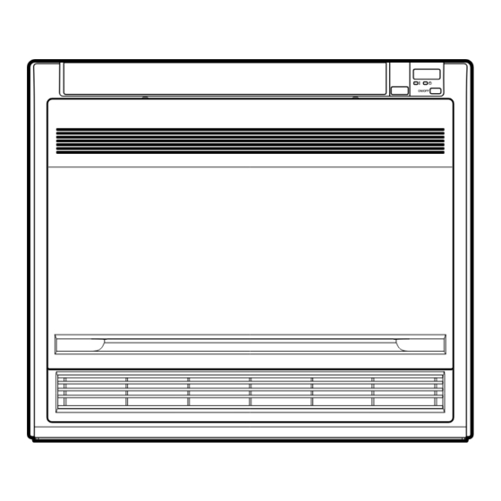
HEAT PUMP CONVECTOR
Models
FWXV15AVEB
FWXV20AVEB
Installation manual
Installationsanleitung
Manuel d'installation
Installatiehandleiding
Manual de instalación
Manuale di installazione
Εγχειρßδιο εγκατÜστασηò
Manual de instalação
Installasjonshåndbok
Installationshandbok
English
Deutsch
Français
Nederlands
Español
Italiano
ΕλληνικÜ
Portugues
Norsk
Svenska
Advertisement
Table of Contents

Related Manuals for Rotex FWXV15AVEB

Summary of Contents for Rotex FWXV15AVEB
- Page 1 INSTALLATION MANUAL DAIKIN HEAT PUMP CONVECTOR Installation manual English Installationsanleitung Deutsch Manuel d’installation Français Installatiehandleiding Nederlands Manual de instalación Español Manuale di installazione Italiano Models FWXV15AVEB Εγχειρßδιο εγκατÜστασηò ΕλληνικÜ FWXV20AVEB Manual de instalação Portugues Installasjonshåndbok Norsk Installationshandbok Svenska...
- Page 2 3SB64418-9C...
-
Page 3: Safety Precautions
Safety Precautions • The precautions described herein are classified as WARNING and CAUTION. They both contain important information regarding safety. Be sure to observe all precautions without fail. • Meaning of WARNING and CAUTION notices WARNING....Failure to follow these instructions properly may result in personal injury or loss of life. CAUTION....Failure to observe these instructions properly may result in property damage or personal injury, which may be serious depending on the circumstances. -
Page 4: Choosing An Installation Site
Accessories – Indoor unit Mounting plate Remote controller holder Piping insulation Titanium apatite photocatalytic Dry battery AAA. LR03 O ring air-purifying filter (alkaline) Drain hose Operation manual Connection pipe Insulation sheet Installation manual Wireless remote controller Binding band * For piping insulation, O ring and connection pipe details, see the valve kit installation manual. - Page 5 Indoor Unit Installation Drawings The indoor unit may be mounted in any of the three styles shown here. Exposed Half concealed Concealed Mounting plate Molding Grid (field supply) Floor Installation Wall Installation Location for securing the installation panel. ( 7 0 0 ) (unit: mm) 1 3 4 6 4 4...
-
Page 6: Installation Tips
Installation Tips Removing and installing front panel • Removal method 1) Slide until the 2 stoppers click into place. 2) Open the front panel forward and undo the string. 3) Remove the front panel. • Installation method 1) Attach the front grille and front panel after pulling the string around them. -
Page 7: Indoor Unit Installation
Indoor Unit Installation (1) Exposed installation Installing indoor unit 3 tabs Front grille Casing Preparation • Open the front panel, remove the 4 screws and dismount the Remove front grille while pulling it forward. front grille • Follow the procedure below when removing the slit portions. Front panel Open the front panel. - Page 8 3-2. Drain piping 1) Use commercial rigid polyvinyl chloride pipe (general VP 20 pipe, outer diameter 26mm, inner diameter 20mm) for the drain pipe. 2) The drain hose (outer diameter 18mm at connecting end, 220mm long) is supplied with the indoor unit. Prepare the drain pipe picture below position.
- Page 9 Indoor Unit Installation (1) Wiring • Lift the sensor securing plate, remove the front metal plate cover, and connect the branch wiring to the terminal block. 1) Strip wire ends (15mm). 2) Connect the power supply wire to the terminal block of main wiring box securely. 3) Connect the earth wires to the corresponding terminals.
- Page 10 When connecting to a sub electrical wiring box 6-1. Procedure for connecting [Figure 1] From the main To the main electrical main electrical wiring box electrical wiring wiring box with sub electrical wiring box Along the wires to the ceiling. 1) Turn off the “altherma”...
- Page 11 Indoor Unit Installation (1) Purging air ■Purging air • Air pockets sometimes form in the piping during trial operation Knob Air purge valve after construction work and during normal operation. To remove air pockets from inside the piping, follow the steps below to purge air from the unit.
- Page 12 Indoor Unit Installation (2) Half concealed installation Only items peculiar to this installation method are given here. See exposed installation for additional instructions. Wall hole 670-690 (unit: mm) • Drill a wall hole of the size shown in the illustration on the right. Open size Opening hole Floor...
-
Page 13: Concealed Installation
Indoor Unit Installation (3) Concealed installation Only items peculiar to this installation method are given here. See exposed installation for additional instructions. Install the unit according to the instructions below. Failure to do so may cause lead to both cooling and heating failure and the condensation inside the house. -
Page 14: Test Items
Changing upward airflow DIP switch Change the upward airflow DIP • How to set and use the switch switch (SW2-4) to “ON” to limit the Switch number SW2-4 upward airflow. 1) Remove the front grille. Set function Upward airflow limit 2) Switch the DIP switch (SW2-4) on the PCB in the electrical wiring box to “ON”. - Page 15 Two-dimensional bar code is a code for manufacturing. 3P257982-1 M09B169 (0912) HT...
Need help?
Do you have a question about the FWXV15AVEB and is the answer not in the manual?
Questions and answers