
Summary of Contents for REGULA medius 600 SR
- Page 1 Controller unit for solar thermal systems medius 600 SR Installation and operating instructions English version of original German installation and operating instructions Version: 1.0 July 2012...
- Page 2 • These installation and operating instructions will hereinafter be designated as "Instructions". • The medius 600 SR controller will hereinafter be designated as "Controller". • The thermal solar power plant will hereinafter be designated as "Solar power plant".
- Page 3 This manual is designed to help you use the controller properly, safely and economically. Target group This manual is addressed to all persons who carry out any of the following tasks: • Installing the controller • Connecting the controller • Putting the controller into operation •...
- Page 4 Style conventions used in the text Specific style conventions are assigned to different elements in the manual. This makes it easy to recognise the type of text concerned: Standard text, "Menu", "Menu item", "Button designations", • lists and actions. Notes accompanied by this symbol contain information about how to operate the controller economically.
-
Page 5: Table Of Contents
Table of contents Safety ........................7 1.1 Proper use .............................. 7 1.2 Basic safety information ........................7 Description of the controller ................... 9 2.1 Overview ..............................9 Installing the controller ..................10 3.1 Fastening the controller ........................11 Connecting the controller ..................12 4.1 Connecting cables to the controller .................... - Page 6 Setting protective functions .................. 47 9.1 Setting the "Collector protection" function ................47 9.2 "Storage tank protection" function ....................48 9.3 "System protection" function ......................48 9.4 "Pump protection" function......................48 9.5 "Heat exchanger protection" ......................48 9.6 Setting the "Recooling" function ....................49 9.7 Setting the "Drain-back"...
-
Page 7: Safety
Safety 1 Safety This chapter contains information on: • the proper use of the controller and • the safe use of the controller. Read this chapter through carefully before you install, connect or operate the controller. 1.1 Proper use The controller is used for monitoring and controlling a solar thermal system. Appropriate use of the controller includes the following requirements: •... - Page 8 Safety Preventing risks of fatal injury from electric shocks • Make sure that all regulations applicable at the point of use are complied with. • Always make sure that the controller is disconnected from the power supply before carrying out any work on it. •...
-
Page 9: Description Of The Controller
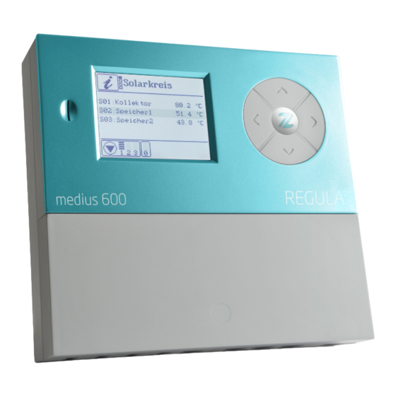
Description of the controller • When in "manual mode", the system must only ever be operated for a short time and only for test purposes. • Install sensor lines separately from 230 V lines. • Use only sensor connection boxes supplied by the manufacturer. 2 Description of the controller The controller is used for monitoring and controlling a solar thermal system. -
Page 10: Installing The Controller
Installing the controller For data exchange purposes the controller is equipped with a microSD card interface (1). 3 Installing the controller DANGER Risk of fatal injuries due to explosions or fire. Never use the controller in areas where there is a risk of explosion. ... -
Page 11: Fastening The Controller
Installing the controller 3.1 Fastening the controller If you wish to lead cables and lines through the back of the controller, you need to do this before you fasten it. ATTENTION Risk of damage to the controller housing due to screws tightened too firmly. -
Page 12: Connecting The Controller
Connecting the controller 4 Connecting the controller DANGER Risk of fatal electric shock when working on the opened controller. Make sure that the controller is disconnected from the mains voltage before removing the terminal cover. Make sure that the power supply has been secured to prevent it from being switched on again. - Page 13 Connecting the controller The following illustration shows the elements of the controller that are important for connection: Pos. Description Terminals for extra-low voltage area Fuse Terminals for 230 V area Terminals for protective conductor Terminals for relay contact Cut-out apertures for cable feedthrough at the back Screw clamps for securing the cables Cut-out apertures for cable feedthrough on the underside...
-
Page 14: Connecting The Controller To The Power Supply
Connecting the controller Connect the cables to the corresponding terminals. Information about connecting the system components to the corresponding terminals can be found in the section Assignment of the terminals to the system components from page 15 onwards. Screw the terminal cover securely back in place. 4.2 Connecting the controller to the power supply When making the mains connection, you must ensure that the mains supply can be disconnected at any time. -
Page 15: Assignment Of The Terminals To The System Components
Connecting the controller 4.4 Assignment of the terminals to the system components For orientation when assigning the terminals to the switching outputs, various different hydraulic layouts are shown in the following. These show simplified solar circuits that you can use with the controller. The process water circuit is not shown here. For the hydraulic layouts you can select "External heat exchanger"... - Page 16 Connecting the controller Terminal assignment for hydraulic layout 110.00 Hydraulic layout 110.00 Hydraulic layout 111.00 Hydraulic layout 112.00 Terminal R1 + N + PE Solar circuit pump (R2 + N + PE) 111.00: Secondary pump 112.00: Three-way valve for bypass function S1 + S1 Temperature sensor for collector S2 + S2...
- Page 17 Connecting the controller Terminal assignment for hydraulic layout 210.01 Hydraulic layout 210.01 Alternative layout Hydraulic layout 211.01 Hydraulic layout 212.01 Terminal R1 + N + PE Solar circuit pump R2 + N + PE Three-way valve (R3 + N + PE) 211.01: Secondary pump 212.01: Three-way valve for bypass function S1 + S1...
- Page 18 Connecting the controller Terminal assignment for hydraulic layout 210.02 Hydraulic layout 210.02 Alternative layout Hydraulic layout 211.02 Terminal R1 + N + PE Pump for storage tank 1 R2 + N + PE Pump for storage tank 2 (R3 + N + PE) 211.02: Solar circuit pump S1 + S1 Temperature sensor for collector...
- Page 19 Connecting the controller Terminal assignment for hydraulic layout 120.01 Hydraulic layout 120.01 Hydraulic layout 121.01 Hydraulic layout 122.01 Terminal R1 + N + PE Solar circuit pump R2 + N + PE Three-way valve (R3 + N + PE) 121.01: Secondary pump 122.01: Three-way valve for bypass function S1 + S1 Temperature sensor for collector 1...
- Page 20 Connecting the controller Terminal assignment for hydraulic layout 120.02 Hydraulic layout 120.02 Hydraulic layout 121.02 Hydraulic layout 122.02 Terminal R1 + N + PE Pump for collector 1 R2 + N + PE Pump for collector 2 (R3 + N + PE) 121.02: Secondary pump 122.02: Three-way valve for bypass function S1 + S1...
- Page 21 Connecting the controller Terminal assignment for hydraulic layout 000.00 In layout 000.00 you can use all outputs as multi-function controllers. In this case you must define at least one of the four switching outputs R0, R1, R2 or R3 as a multi-function controller.
-
Page 22: Operating The Controller
Operating the controller 5 Operating the controller This chapter provides you with an overview of the controller's display elements and operating elements. This is followed by explanations of all the basic actions. 5.1 Description of the display elements The following menu symbols are displayed in the top part of the display in the main menu: Main menu Symbol... - Page 23 Operating the controller The menu symbol (1), menu level (2) and the name of the active menu level (3) are displayed in the top part of the display. The middle part of the display shows menu items in list form. The names of the menu items (7) are displayed on the left-hand side. On the right-hand side you will see the current values or status messages (4) for each of the menu items.
-
Page 24: Using The Operating Buttons
Operating the controller 5.2 Using the operating buttons The operating buttons allow you to navigate in the menus and make changes to values. The following table explains the functions of the operating buttons: Operating Function buttons Move up in the list. Increase the displayed value. - Page 25 Displaying and changing the values in the menus Changing values To activate a menu item, select The "Change value" display screen will be displayed. The value will be displayed as a figure (1) and as a bar display (2). The bar display shows the setting range (In this case: 15–95 °C). ...
-
Page 26: Displaying And Changing The Values In The Menus
Displaying and changing the values in the menus 6 Displaying and changing the values in the menus This chapter provides an overview of the menus and menu items. Menu items for the first menu level are displayed in bold . Menu items for the second menu level are displayed beneath in standard text. - Page 27 Displaying and changing the values in the menus Pos. Description Current measured value Display of the minimum value reached so far Display of the maximum value reached so far Reset the minimum and maximum values to the current measurement value To reset a value, proceed as follows: ...
- Page 28 Displaying and changing the values in the menus Balance values This menu allows you to display the following balance values and, if necessary, reset them: • Operating hours (resetting is possible) • Output (resetting is possible) • Flow For systems with two storage tanks, the tanks are denoted by the digits "1" and "2" respectively.
-
Page 29: Displaying And Changing Values In The "Program" Menu
Displaying and changing the values in the menus 6.2 Displaying and changing values in the "Program" menu The "Program" menu allows you to display and change the parameters. The "Current settings" column allows you to enter your settings. WARNING Risk of scalding from hot water as a result of incorrect settings. ... - Page 30 Displaying and changing the values in the menus Menu item Description Range Factory Current settings setting Target Required temperature for the "Target 15–85 °C 40 °C temperature temperature" charging principle Radiation Value at which the "Tube collector" 0–500 W 100 W or "Drain-back"...
- Page 31 Displaying and changing the values in the menus Menu item Description Range Factory Current settings setting Time 1–3: Stop Stop time for time windows 1-3. 00:00–24:00 00:00 When the stop time for time window 1 has been specified, you can specify the stop times for time windows 2 and 3.
-
Page 32: Controlling Switching Outputs In The "Manual Mode" Menu
Displaying and changing the values in the menus 6.3 Controlling switching outputs in the "Manual mode" menu The "Manual mode" menu allows the controller's switching outputs to be turned on and off for test purposes. To enable the controller to run in automatic mode again, you have to exit manual mode after completion of setting tasks. - Page 33 Displaying and changing the values in the menus There are two operating modes: • User mode • Editing mode In user mode you can display values in this menu, but you cannot make any changes to them. If user mode is activated, the menu symbol is displayed in the form of a "locked" symbol.
- Page 34 Displaying and changing the values in the menus Menu item Description Range Factory Current settings setting Parallel Switch the "Parallel charging" charging function on or off Charging DeltaT DeltaT principle (temperature- difference) Target temperature Collector protection Function Switch the "Collector protection" function on or off Temperature Temperature at which the "Collector...
- Page 35 Displaying and changing the values in the menus Menu item Description Range Factory Current settings setting delta T Temperature for control via 1.0 °C–5.0 °C 1.0 °C temperaturechange Anti-freeze protection Function Switch the "Anti-freeze protection" function on or off Sensor Select the sensor input S1–S6 Temperature...
- Page 36 Displaying and changing the values in the menus Menu item Description Range Factory Current settings setting Glycol type Select the glycol type for the coolant. Anro, Ilexan Anro EG/E/P, Antifrogen L/N, Tyfucor L5.5/LS, Dowcal 10/20/N Glycol Mixing ratio for the coolant 0–100 % 50 % concentration...
- Page 37 Displaying and changing the values in the menus Menu item Description Range Factory Current settings setting Waiting time Duration of waiting time for the 1–60 min 15 min "Time-controlled circulation" function Link Logical linking of the output to the R1: 0, 1, x xxxx other outputs R2: 0, 1, x...
-
Page 38: Setting The Control Functions
Setting the control functions 7 Setting the control functions The general control functions allow you to configure the settings for the charging of the storage tanks. You can set the following control functions: • Charging principle • "Storage tank priority" function •... -
Page 39: Setting The "Storage Tank Priority" Function
Setting the control functions 7.2 Setting the "Storage tank priority" function This function is only available for dual tank systems. The "Storage tank priority" function controls the tank charging of dual tank systems. There are the following types of dual tank systems: •... -
Page 40: Setting The Pump Control System
Setting the control functions 7.4 Setting the pump control system You can connect standard pumps and high-efficiency pumps (HE pumps). For these you can set the following types of control system: • 230 V block modulation (standard pumps) • Analog control (HE pumps) •... - Page 41 Setting the control functions The following diagram shows the power curve for the pump control system with analog signal. n (%) – Pump output U (V) – Output voltage Controlling HE pumps with PWM signals In the case of the pump control system with PWM signal, the controller sends a PWM signal (pulse width modulation signal) to terminals HE1 and HE2.
-
Page 42: Setting The "Tube Collector" Functions
Setting the control functions In the case of the pump control system with an inverted PWM signal, the nominal speed of the pump (0–100 %) corresponds to the PWM signal (100-0 %). The following diagram shows the power curve for the pump control system with an inverted PWM signal at a minimum pump output of 30 %. -
Page 43: Bypass Function / External Heat Exchanger
Setting multi-function controllers (MFC) For this function you can set the following parameters: • Basic settings/Solar circuit/Tube collector/Pump runtime • Program/Solar circuit/Radiation Control via temperature change Whenever the collector temperature rises by a predefined value within a predefined interval period, the solar circuit pump will be switched on. For this function you can set the following parameters: •... -
Page 44: Setting The "Cooling" Function
Setting multi-function controllers (MFC) You can select the function for the required multi-function controller in: • Basic settings/MFC R0 –R3/Function 8.1 Setting the "Cooling" function In the case of the "Cooling" function, the switching output of the multi-function controller switches on as soon as the preset switch-on temperature is exceeded. If the temperature drops below the lower limit of the preset temperature range (hysteresis), the switching output of the multi-function controller switches off. -
Page 45: Setting The "Threshold Value Switch" Function
Setting multi-function controllers (MFC) For this function you can set the following parameters: • Basic settings/MFC R0–R3/Sensor source • Basic settings/MFC R0–R3/Sensor sink • Program/MFC R0–R3/Tmax sink • Program/MFC R0–R3/Diff. controller max • Program/MFC R0–R3/Tmin source • Program/MFC R0–R3/Diff. controller min •... -
Page 46: Setting The "Circulation" Function
Setting multi-function controllers (MFC) 8.7 Setting the "Circulation" function This function provides you with hot water at all times. You can choose from the following control types: • Temperature-controlled • Time-controlled Temperature-controlled The switching output of the multi-function controller switches on as soon as the temperature falls below the preset setpoint temperature. -
Page 47: Setting The Logical Link
Setting protective functions 8.10 Setting the logical link In principle, all MFC can be linked with other outputs. This means that the status of another output will influence the control operation of the respective MFC. Example for MFC R3: The value 10XX is entered in the "Basic settings" – MFC - Link menu. Assignment: This would mean that MFC R3 would only be active if: •... -
Page 48: Storage Tank Protection" Function
Setting protective functions For this function you can set the following parameters: • Basic settings/Solar circuit/Collector protection 9.2 "Storage tank protection" function If a hydraulic layout with two storage tanks is used, the "Storage tank protection" function will be automatically active and cannot be changed. This function protects the storage tanks against overheating caused by faulty wiring or any other possible faults. -
Page 49: Setting The "Recooling" Function
Setting protective functions This function protects the heat exchanger against damage from frost. Whenever the temperature on the collector falls below 5 °C, the heat exchanger pump switches on. 9.6 Setting the "Recooling" function ATTENTION Risk of damage to the solar power system if operated with the "Recooling" function in combination with reheating. -
Page 50: Setting The "Anti-Freeze Protection" Function
Measuring energy output You can choose between the control types "Time-controlled" and "Radiation-controlled". Time-controlled You can set a time window and a pump runtime. In the time window the solar circuit pump is switched on at certain specific intervals for the duration of the preset pump runtime. -
Page 51: Dfg (Flow Sensor)
Measuring energy output For the energy output measurement you can set the following parameters: • Basic settings/Output measurement You can choose from the following measurement principles: • DFG (Flow sensor) • VFS (Vortex flow sensor) • DFA (Flow indicator) 10.1 DFG (Flow sensor) The flow sensor measures the flow rate mechanically. -
Page 52: Restore Factory Settings
Restore factory settings 11 Restore factory settings ATTENTION Risk of loss of current settings due to incorrect restoration of the factory settings. Before restoring the factory settings, make sure that you no longer require the current settings. If necessary, save the current settings to a microSD card before restoring the factory settings. -
Page 53: Faults
Faults 13 Faults ATTENTION Risk of damage to the system if faults are remedied incorrectly. Make sure that faults are only ever remedied by specialist personnel. There are two categories of system faults: • Faults that are detected by the controller and trigger a fault message •... - Page 54 Faults The table below shows the faults with fault messages: Fault message Possible cause Action Interruption A sensor line is Make sure that the sensor interrupted. line is intact. Additional symbol indicator in "Info"/"Solar circuit" A sensor is faulty. Check the sensor resistance.
-
Page 55: Faults Without Fault Message
Faults Fault message Possible cause Action A sensor line is faulty. Make sure that the sensor line is intact. Faulty pump connection Make sure that the pump line. wiring is intact. A pump is faulty. Replace the pump. There is air in the system. Vent the system. - Page 56 Faults Fault Possible cause Action The pump fails to switch on. Manual mode has been Exit manual mode. activated. The preconditions for the Wait until the preconditions pump to be switched on have for the pump to be switched not been met. on have been met.
-
Page 57: Technical Data
Technical data 14 Technical data Autonomous electronic temperature difference controller, continuous operation Housing material 100% recyclable ABS housing Dimensions L x W x D in mm 176 × 162 × 44 Protection class IP30 according to DIN 40050, EN 60529 Operating voltage AC 230 voltage, 50 Hz, –10 to +15% Power consumption... -
Page 58: Accessories
Accessories Autonomous electronic temperature difference controller, continuous operation Protection Microfuse TR 5 type 372, 2 A/T (2 ampere, slow) Ambient temperature 0 to +40 °C Storage temperature -10 to +60 °C 15 Accessories The following accessories are available for this controller: •... -
Page 59: Disposing Of The Controller
Disposing of the controller 16 Disposing of the controller The environmentally-friendly disposal of electronic assemblies, recyclable materials and other unit components is regulated by national and regional laws. Contact the competent local authority for detailed information on disposal. Dispose of lithium batteries in accordance with the statutory regulations. ... - Page 60 These instructions were prepared by a technical documentation office certified by DocCert-System. Address of manufacturer Prozeda GmbH In der Büg 5 D-91330 Eggolsheim Telephone: +49(0)9191/6166-0 Telefax: +49(0)9191/ 6166-22 Email: kontakt@prozeda.de www.prozeda.de 1335B-TB002-10B-E...
Need help?
Do you have a question about the medius 600 SR and is the answer not in the manual?
Questions and answers