Table of Contents
Advertisement
Quick Links
Control panel
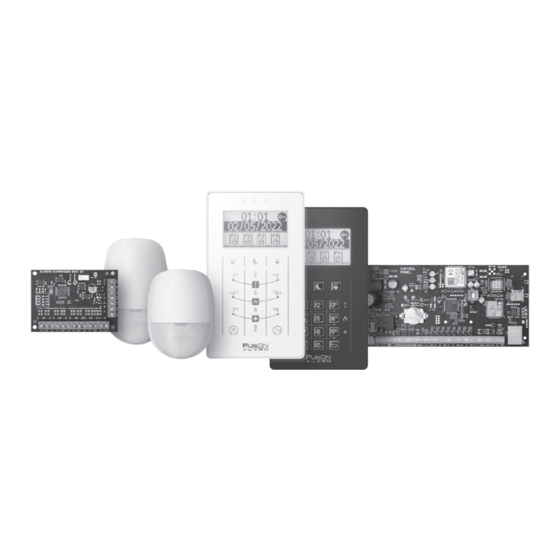
PulsON Alarm 4G
Installer's manual
ALARM SYSTEM
PulsON Alarm 4g v.1.0
www.pulsonalarm.pl
NSS Sp. z o.o. ul. Modularna 11 (Hala IV), 02-238 Warszawa
tel. +48 882 481 935, e-mail: kontakt@pulsonalarm.pl
NIP: 521-312-46-74
Copyright © NSS Sp. z o. o.
Copyright © NSS Sp. z o. o.
EN
Update: 3.11.2022
Advertisement
Table of Contents

Related Manuals for NSS PulsON Alarm 4G

Summary of Contents for NSS PulsON Alarm 4G
- Page 1 Installer’s manual ALARM SYSTEM PulsON Alarm 4g v.1.0 www.pulsonalarm.pl NSS Sp. z o.o. ul. Modularna 11 (Hala IV), 02-238 Warszawa tel. +48 882 481 935, e-mail: kontakt@pulsonalarm.pl NIP: 521-312-46-74 Copyright © NSS Sp. z o. o. Copyright © NSS Sp. z o. o.
-
Page 3: Table Of Contents
PULSON ALARM 4G ALARM SYSTEM V.1.0 TABLE OF CONTENTS Introduction ..............................General information about the system ......................Compatible devices ............................ Purpose of the system ..........................Technical specifications ..........................Technical specifications ..........................Mainboard description ..........................Pinout description ............................Power supply performance on the motherboard .................. - Page 4 PULSON ALARM 4G ALARM SYSTEM V.1.0 Event groups ............................... 27 Communication options ..........................28 Users ................................29 Users ................................29 Access code options ..........................29 Codes ................................29 Clip ................................30 Monitoring station ............................31 Alarms ................................. 31 Arming/disarming – users ........................... 31 Arming/disarming –...
-
Page 5: Introduction
The PulsON Alarm 4G control panel, the PulsON EXP8 / 1 expansion modules and the PulsON LCD / C and PulsON LCD / T keypads meet the requirements of the EN-50131 standard for Grade2. -
Page 6: Technical Specifications
PULSON ALARM 4G ALARM SYSTEM V.1.0 TECHNICAL SPECIFICATIONS Technical data PulsON Alarm 4G Number of lines on the control panel mainboard Maximum number of lines Maximum number of line expansion modules Number of outputs on the control panel board Maximum number of outputs... -
Page 7: Pinout Description
PULSON ALARM 4G ALARM SYSTEM V.1.0 Signal strength This section is described in detail in the GSM measurement and Wi-Fi signal strength test chapter section A function designed to protect the battery against deep discharge (below 10.5V). Funkcja If the jumper is: NON-PROTECTED –... -
Page 8: Menu Navigation
PULSON ALARM 4G ALARM SYSTEM V.1.0 MENU NAVIGATION PulsON LCD/C PulsON LCD/T To navigate the menu on the main screen and in the user and installer menu, use the navigation arrows on the buttons 2 (up), 0 (down), 4 (left) and 6 (right), and the buttons... -
Page 9: Characteristics Of Bus Connections
PULSON ALARM 4G ALARM SYSTEM V.1.0 CHARACTERISTICS OF BUS CONNECTIONS All 4 control panel terminals must be connected to the bus clamps in the extension modules and manipulators. The cable used for connections should have a minimum cross -section of 0.5 mm2. The maximum length of the cable used to connect the module to the communication bus is 305 m. -
Page 10: Connection Of Detection Lines
Connection to the electrical system must be made in accordance with the applicable standards and legal regulations.. Connection of detection lines In the PulsON Alarm 4G system, there are four types of parameterization of detection lines • NC • NO •... - Page 11 PULSON ALARM 4G ALARM SYSTEM V.1.0 Recognized faults The system monitors the system parameters on an ongoing basis. If any irregularities are detected, information about the trouble is displayed on the keypad, and an appropriate reporting code is sent to the alarm monitoring station.
- Page 12 PULSON ALARM 4G ALARM SYSTEM V.1.0 Check connections at the control panel The EOL or DEOL line is shorted to ground. and in the detector. Check the cable. Line fault Wrong type of line parameterization or re- Change the line parameterization set- sistance in installer programming selected.
-
Page 13: Description Of Control Panel Functions
PULSON ALARM 4G ALARM SYSTEM V.1.0 In parallel with the signal force using the LED on the control panel, after pressing the switch on the board, signal strength and access to services is shown in decibels on the cental panel manipulators. The -64 dB to -78 dB signal is about 50% of the range. -
Page 14: System
PULSON ALARM 4G ALARM SYSTEM V.1.0 SYSTEM The System section contains all the control panel parameters that define the operation of the entire system. General settings Compliance with the norm EN-50131:Grade2 Enabling EN-50131 compliance will change the following settings: Default: NO 1. -
Page 15: Parameterization Selection
PULSON ALARM 4G ALARM SYSTEM V.1.0 Parameterization selection EOL resistor The value of the EOL resistor used in the EOL line configuration 1k, 1.1k, 2.2k, 2.7k, (with a single resistor). 3.3k, 3.74k, 4.7k, • Normal condition = EOL 5.6k, 6.8k, 6.98k, 10k •... -
Page 16: Service Settings
PULSON ALARM 4G ALARM SYSTEM V.1.0 Sabotage sound The function defines how the tamper of the alarm system will be signaled. Cichy, • Bell, • Silent Just a silent alarm • Buzzer, • Bell Activation of the output defined as BELL •... -
Page 17: Lines
PULSON ALARM 4G ALARM SYSTEM V.1.0 LINES Line reaction types Line reaction types define how the line will behave. There are 22 different line types available in the system. To be able to program zone related functions, first select the zone reaction type (for an Unused zone, zone programming is not possible). -
Page 18: Assigning Lines To Partitions
PULSON ALARM 4G ALARM SYSTEM V.1.0 Momentary key on / off A momentary violation of NC, NO and EOL zones causes alternate arming / disarming of the partition to which the zone is assigned. Permanent switch on / off Violation of the zone causes permanent arming / disarming of the partition to which the zone is assigned. NC and EOL zone: closed = system disarmed;... -
Page 19: Zone Response Time
PULSON ALARM 4G ALARM SYSTEM V.1.0 Buzzer arming / silent disarming Violation of a zone with the selected signaling function Buzzer arming / silent disarming, in the case of a system in supervision, triggers acoustic signaling in keypads, and in the case of a disarmed system, it does not trigger any sound signals. -
Page 20: Violation Counter
PULSON ALARM 4G ALARM SYSTEM V.1.0 Violations Counter The option determines how many line violations are needed to generate an alarm - this option is related to the “Violations during time periods” parameter. Violations during time periods The option defines the time in which a line violation must occur in order to trigger a loud alarm - the option is related to the “Violations counter”... - Page 21 PULSON ALARM 4G ALARM SYSTEM V.1.0 Function key programming options available Button not used No response to button selection Check for faults After pressing the button, the user will go to the fault checking menu after entering the user code...
-
Page 22: Schedules
PULSON ALARM 4G ALARM SYSTEM V.1.0 SCHEDULES The schedules enable automatic, clock-controlled arming (including arming in night mode) and disarming of partitions as well as control of utility outputs. Two schedules must be used to obtain the on / off operation. - Page 23 PULSON ALARM 4G ALARM SYSTEM V.1.0 • GSM failure The output will be activated if the GSM module cannot be logged into the network. • No GSM coverage The output will be activated when there is no GSM network coverage.
-
Page 24: Communication
PULSON ALARM 4G ALARM SYSTEM V.1.0 • System status – armed The output will be activated if the partitions assigned to it are armed – regardless of arming mode (total / night). • System State – Armed in Exit Mode An output will activate if all assigned partitions are armed in exit mode. -
Page 25: Monitoring
Cloud address In order to use the mobile application, the cloud settings must be properly configured. By default, the control panel uses the manufacturer’s cloud to connect to the address nss.pulsonalarm.pl on port 8883. Copyright © NSS Sp. z o. o. -
Page 26: Sms Notifications
PULSON ALARM 4G ALARM SYSTEM V.1.0 Cloud port The port used to connect to the cloud server. SMS notifications The purpose of SMS notifications is to inform the user about the occurrence of a specific event in the alarm system. - Page 27 PULSON ALARM 4G ALARM SYSTEM V.1.0 Line blocking The function defines whether the user has the right to bypass the line. Access from the mobile application The function defines whether the user has access to the mobile application. Controlling the outputs The function defines whether the user can control the outputs.
- Page 28 PULSON ALARM 4G ALARM SYSTEM V.1.0 MONITORING STATION The tabs offer event codes in the Contact ID protocol and the option to select events for SMS notifications. Alarms The following alarm event codes are provided: panic, fire, medical, duress, control panel tamper, panic.
- Page 29 PULSON ALARM 4G ALARM SYSTEM V.1.0 Outputs The tab makes it possible to test the outputs existing in the system in real mode. In order to test the outputs, press the ON and / or OFF buttons. The current status of the output will be displayed in the STATUS column.
- Page 30 PULSON ALARM 4G ALARM SYSTEM V.1.0 Copyright © NSS Sp. z o. o.
- Page 31 PULSON ALARM 4G ALARM SYSTEM V.1.0 Copyright © NSS Sp. z o. o.
- Page 32 PULSON ALARM 4G ALARM SYSTEM V.1.0 APPENDIX 1 – INSTALLATION TEMPLATE Manipulator LCD/C Copyright © NSS Sp. z o. o.
- Page 33 PULSON ALARM 4G ALARM SYSTEM V.1.0 APPENDIX 2 – INSTALLATION TEMPLATE Manipulator LCD/T Copyright © PULSON Sp. z o. o.
- Page 34 PULSON ALARM 4G ALARM SYSTEM V.1.0 APPENDIX 3 – METHOD OF INSTALLATION FOR LCD/C AND LCD/T KEYPADS Manipulator LCD/C KLIK! Manipulator LCD/T KLIK! Copyright © NSS Sp. z o. o.
- Page 36 No reproduction of this manual, in whole or in part (except for brief quotations in critical articles or reviews), may not be made without the written permission of NSS Ltd. NSS Sp. z o.o. ul. Modularna 11 (hala IV) 02-238 Warszawa Update: 3.11.2022...
Need help?
Do you have a question about the PulsON Alarm 4G and is the answer not in the manual?
Questions and answers