Table of Contents
Advertisement
Quick Links
Advertisement
Table of Contents

Subscribe to Our Youtube Channel
Summary of Contents for Kongskilde CFG 20
- Page 1 CFG 20/CFG 40 Chain elevator Manual & Spare parts list...
-
Page 2: Table Of Contents
Contents Contents ..............................2 Introduction ..............................4 EU Declaration of conformity ........................5 Conditions for use............................6 General information ............................ 7 Delivery ............................. 7 Storage .............................. 7 Noise level measuring ........................7 Type plate ............................8 Construction ............................8 Capacity ............................9 Technical specifications – power consumption ................ - Page 3 Chain elevator with auger trough ............33 Chain elevator with 55° and 90° bend ..........34 Fitting of gear motor ................35 Fitting of motor and pulley kit ..............36 Elevator extensions ................37 Elevator chain ..................38 Assembly of elevator ................41 Potential equalization ................42 Height attachment ................. 43 Support of increasing elevator .............. 44 Upstart ....................45 Elevator stops – faultfinding ..............
-
Page 4: Introduction
Introduction Important! Please read these instructions carefully before assembly and use. -
Page 5: Eu Declaration Of Conformity
EU Declaration of conformity The manufacturer: JEMA AGRO A/S Kløservejen 2, Sahl DK-8850 Bjerringbro Phone +45 86 68 16 55 Hereby declares that: Product: Chain elevator Type: CFG 20/CFG 40 (T20/T40) Year of production: 2006 • Conforms to the Machine directive 2006/42/EF with special reference to the directive appendix 1 regarding major health- and safety regulations regarding construction and production of the machines The following standards have been applied: EN ISO 12100-1:2005 Basic terminology and methodology EN ISO 12100-2:2005... -
Page 6: Conditions For Use
Conditions of use Kongskilde Industries A/S chain elevators CFG 20/CFG 40 have been constructed for transport of grain, granular materials and seed mix. • The chain elevators CFG 20/CFG 40 must only be used for the product(s) specified in the contract. • The electrical connections must be done by a qualified electrician. • The chain elevators CFG 20/CFG 40 must be potential adjusted in accordance with the current local regulations • The chain elevators have been thoroughly controlled regarding maintenance, and a checklist has been drawn up containing regular cleaning- and maintenance intervals. If these intervals are not observed, the Kongskilde Industries A/S conditions for a trouble-free operation cease to exist and the warranty will be invalid. • During installation, maintenance or repair the electric supply to the chain elevators must be disconnected and secured against accidental reconnection. • The user manual must be kept / be available in close proximity to the chain elevator CFG 20/CFG 40. -
Page 7: General Information
General information Delivery The chain elevator is disassembled for shipment. Standard packing (pallet/wooden boxes, grid boxes, etc.) Regarding the actual transport there are no specific requirements apart from normal consideration. The shipment includes the parts stated in the order confirmation. Please read this manual carefully before installation and use. Storage There are no precautions regarding long-time storage. After delivery the components must be kept in a suitable, dry storage area before installation. Noise level A noise level test was conducted for the chain elevator. The level has been measured in a dis- tance of 1 m from the conveyor surface and at a height of 1.6 m from the floor level. During the test the chain elevator was running unloaded, which is the operational state of maximum noise level. The measured noise level is not higher than 70 dB... -
Page 8: Type Plate
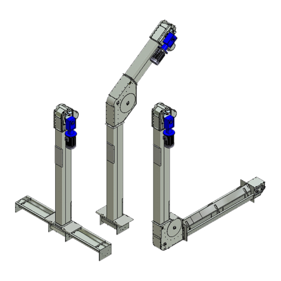
Type Plate The type plated is fitted on the drive station. Type: XXXXX Model: XXXX JEMA AGRO A/S Sahl, DK-8850 Bjerringbro tlf. +45 86 68 16 55 År: XXXX www.jema.as Construction The chain elevator type CFG 20/CFG 40 is made up of standard elements, which can be combined and easily integrated into all grain conveyor systems. It is characterized by a large capacity and compact dimensions. Both elevators work efficiently in all positions and compared to their capacity (output), they both have low power consumption. The chain elevator is made of galvanized steel, which makes it perfectly suited for outdoor use. It is furthermore fitted with a high quality roller chain with bolted rubber flights. The chain elevator can be combined for both vertical and horizontal transport by using side augers in troughs. These are driven from the elevator bottom shaft, so both elevator and side auger are driven by the same motor, alternatively the side auger can by driven separately by a directly connected gear motor. -
Page 9: Capacity
Capacity The table below shows the various density capacities: Density CFG 20 (33 m CFG 40 (60 m 650 kg. pr. m 21 t/h 39 t/h 700 kg. pr. m 23 t/h 42 t/h 750 kg. pr. m (wheat) 25 t/h 45 t/h Measured in cleaned, storable material at a power supply of 50 Hz The capacity varies according to the nature of the material. Capacity for chain elevator CFG 20/CFG 40: CFG 20 inlet from both sides without propeller 14 t/h CFG 20 inlet from both sides with propeller... -
Page 10: Technical Specifications - Power Consumption
Inlet trough adjustment Capacity Capacity CFG 20 CFG 40 opening opening Pulley drive with Pulley drive with motor 1,500 rpm motor 1,500 rpm Gear motor Gear motor 280 rpm 280 rpm Pulley drive with Pulley drive with motor 1,000 rpm motor 1,000 rpm Gear motor Gear motor 180 rpm 180 rpm The capacity is measured at a density of 750 kg/m³. Important! –... - Page 11 Length Heigth, 2.35 m 3.35 m 4.35 m metres CFG 20/CFG 40 CFG 20/CFG 40 CFG 20/CFG 40 3.65 2.2/3.0 2.2/3.0 2.2/3.0 4.61 2.2/3.0 2.2/3.0 2.2/3.0 5.61 2.2/3.0 2.2/3.0 3.0/3.0 6.61 2.2/3.0 3.0/3.0 3.0/4.0 7.57 3.0/3.0 3.0/4.0 3.0/4.0 8.57 3.0/4.0 3.0/4.0 4.0/4.0 9.66 3.0/4.0 4.0/4.0 4.0/4.0 10.66 4.0/4.0 4.0/4.0...
-
Page 12: Elevator Head
Elevator head The elevator head is delivered as a complete unit. The motor is supplied separately. Elevator extensions The extensions are available in various lengths: 2.5 m, 2.0 m, 1.0 m, 0.5 m, 0.25 m, 0.125 m. Extensions with inspection doors are available in lengths of 2.5 m. Inlet troughs are available in lengths of: 2.0 m, 1.25 m, 1.0 m, and 0.5 m. The elements can be combined to obtain any lengths - for the vertical elevator with steps of 0.125 m. and with intervals of 0.25 m for the horizontal elevator - up to a total length of 20.0 m. -
Page 13: Elevator Boot
Elevator boot The boot section is fitted in trough from vertical position to 45°. Augers in trough can be fitted to the boot section in one or both sides. Elevator boot with inlet Closed boot Flex-boot section with console and clutch... -
Page 14: Scale Drawing Cfg 20/Cfg 40 (Gear Motor)
Scale drawing CFG 20/CFG 40 (gear motor) CFG 20 OK160 CFG 40 SK200 CFG 20 CFG 40 Measure for trough under elevator Concrete measure for auger in trough Ø135 Fill up the auger trough with dry sand, and then trim around the edges. -
Page 15: Scale Drawing Cfg 20/Cfg 40 90°/55° Bend And Chain Conveyor (Angleveyor)
Scale drawing CFG 20/CFG 40 90°/55° bend and chain conveyor (Angleveyor) (gear motor) CFG 20 1045 CFG 40 1045... -
Page 16: Scale Drawing Cfg 20/Cfg 40 (Pulley Drive)
Scale drawing CFG 20/CFG 40 (pulley drive) CFG 20 OK160 CFG 40 Ø200... -
Page 17: Upon Receipt
Upon receipt Please check that all parts and components are included in the shipment and check for possible transport damages. NB: Make sure that the relevant supplier documentation is attached to the gear and motor. In case of missing documentation, please contact Kongskilde Industries A/S – remember to state the order no. Remember all necessary safety equipment before installation. Please read this manual carefully before assembly or installation work begins. Warning labels The chain elevator is fitted with warning labels. Warning! The covers and shields must never be opened or removed, when the machine is working. Warning! Always keep hands away from rotating augers/propellers. -
Page 18: Foundation
Foundation The chain elevator should be placed on a sufficiently hard, level surface that is able to carry the load in question. Lifting equipment Make sure to have the required SWL-approved lifting equipment/crane, required for the actual job. The lifting equipment must be approved to carry the load in question. The load capacity for the individual components can be found in “Parts list CFG 20/CFG 40” in this manual. The total weight of the machine is stated in the section “Weight table chain elevator CFG 20/CFG 40”. NB: Always make sure that nobody is standing under a suspended load. -
Page 19: Lifting Instructions
Lifting instructions The drawing below shows how to lift the chain elevator using the attached brackets. Lifting point... -
Page 20: Weight Table - Individual Components Cfg 20/Cfg 40
Weight table – individual components CFG20/CFG 40 CFG 20 CFG 40 Weight Description Weight kg Part no. Part no. Drive station for pulley drive 92051577 92052116 Drive station for pinion gear motor, RHS 92051583 92052483 Drive station for pinion gear motor, 92051585 92052485 Tension section 92044095 12.61 92045095 13.77 Elevator boot d135, without chain 92051142 92052142 Elevator boot d135, with ball 92051143 92052143 bearings in sprocket, without chain Elevator boot, closed without chain 92051231 92052231 Flex elevator boot, without chain 92051312 92052312 20,7... - Page 21 Weight table – individual components CFG 20/CFG 40 CFG 20 CFG 40 Weight Description Weight kg Part no. Part no. Extension 0.5 m with side inlet d200 92044130 10.5 92045130 without chain 90° bend without chain with sprocket 92051060 37.00 92052060 42.50 55° bend without chain with sprocket 92051030 35.2 92052030 40.0 Trough under elevator 45/90° 92051056 92051056 Hopper kit with cover for 0.5 m inlet 92044024 92045024 trough Chain complete, running metres 92020028 92040028 Hopper for elevator 92000082 92000082 Inlet d200 40 t/h for flex boot, 92052320 one-way RHS...
-
Page 22: Weight Table Chain Elevator Cfg 20/Cfg 40
Weight table – chain elevator CFG 20/CFG 40 Complete with gear motor, trough under elevator and propeller with pin – LHS & RHS CFG 20 CFG 40 Pinion gear motor 280 Pinion gear motor 280 Height, metres 204.000 221.200 222.000 245.200 240.000 269.200 258.000 299.200 276.000 323.200 294.000 341.200 312.000 365.200 10.0 336.000 394.200 11.0 354.000 418.200 12.0 372.000 442.200 13.0 390.000 460.200 14.0 413.000 495.200 15.0... -
Page 23: Weight Table Chain Elevator Cfg 20/Cfg 40
Weight table – chain elevator CFG 20/CFG 40 Complete with gear motor, 55° bend, trough under elevator, propeller with pin – LHS & RHS CFG 20 CFG 40 Height in metres Pinion gear motor 280 rpm Pinion gear motor 280 rpm 15.0 385.000 476.000 16.0 399.000 496.000 17.0 413.000 516.000 18.0 438.000 536.000 19.0 452.000 556.000 20.0 466.000 576.000 Complete with pulley drive, 55° bend, trough under elevator, propeller with pin – LHS & RHS CFG 20 CFG 40 Motor 1500 rpm Motor 1500 rpm Height in metres pulley kit 71/355... -
Page 24: Weight Table Cfg 20 (Gear Motor)
Weight table –CFG 20 (gear motor) Complete with gear motor, 90° bend and inlet trough. Length 2.0 m. 3.0 m. 4.0 m. Height in metres Motor Motor Motor 280 rpm 280 rpm 280 rpm 256.000 292.000 312.500 274.000 310.000 332.500 292.000 328.000 354.500 310.000 352.000 372.500 334.000 370.000 390.500 352.000 388.000 408.500 10.0 370.000 406.000 431.500... -
Page 25: Weight Table Cfg 20 (Pulley Drive)
Weight table –CFG 20 (pulley drive) Complete with pulley drive, 90° bend and inlet trough. Length 2.0 m 3.0 m 4.0 m Height in metres Motor 1500 rpm Motor 1500 rpm Motor 1500 rpm pulley kit pulley kit pulley kit 259.000 295.000 315.500 277.000 313.000 335.500 295.000 331.000 357.500 313.000 355.000 375.500 337.000 373.000 393.500 355.000 391.000 411.500 10.0... -
Page 26: Weight Table Cfg 40 (Gear Motor)
Weight table –CFG 40 (gear motor) Complete with gear motor, 90° bend and inlet trough. Length 2.0 m 3.0 m 4.0 m Height in metres Motor Motor Motor 280 rpm 280 rpm 280 rpm 298.000 334.000 354.500 316.000 352.000 374.500 334.000 370.000 396.500 352.000 394.000 414.500 376.000 412.000 432.500 394.000 430.000 450.500 10.0 412.000 448.000 473.500... -
Page 27: Weight Table Cfg40 (Pulley Drive)
Weight table –CFG 40 (pulley drive) Complete with pulley drive, 90° bend and inlet trough. Length 2.0 m 3.0 m 4.0 m Height in metres Motor 1500 rpm Motor 1500 rpm Motor 1500 rpm pulley kit pulley kit pulley kit 301.000 337.000 357.500 319.000 355.000 377.500 337.000 373.000 399.500 355.000 397.000 417.500 379.000 415.000 435.500 397.000 433.000 453.500 10.0... -
Page 28: Assembly
Assembly Please check the foundation and the transport direction (location of inlet and outlet), before starting the assembly. It is important to read these instructions carefully before starting the assembly. Check that there is sufficient space available. Attention! Before starting the assembly work, check that the required safety equipment is at disposal, e.g. work gloves, safety footwear, helmet, safety glasses and a lifeline, if necessary. This equipment is not included as standard. Assemble the elevator in two parts, top and bottom section: • The bottom part consists of the elevator boot, 2.5 m extension with inspection door (the assembly of the chain is made through this door) and elevator extensions corresponding to half the height of the elevator. • The top section consists of the elevator head and the remaining number of extensions, and must be assembled with the chain - remember that the overlapping plate must be facing downward. • The elevator extensions with inspection doors must be fitted at the elevator base plate, and the end with inspection door in the return channel must be facing downward. Assemble the top- and bottom section, once the individual sections have been assembled. -
Page 29: Sealing
Sealing All the joints must be sealed with a sealing compound in order to avoid dust and moisture nui- sance. The sealer must be applied at the flanges inside the holes. After sealing the joints must be bolted together. Silicone... -
Page 30: Elevator Bottom Section
Elevator boot section Fit and properly attach the boot part to the foundation. Fit the extensions – remember that the overlapping plate must be facing downward. Overlapping plate... -
Page 31: Elevator Top Section
Elevator top section Assemble the elevator top section on the floor. Fit extensions to the elevator head in dimensions corresponding to half of the total elevator height. When the extensions are fitted, fit the chain with rubber slats (see instructions in the section “Elevator chain”). - Page 32 Warning! It is important to fit a tube of min. 850mm or another type of blocking device to avoid the risk of somebody sticking a hand or arm into the machine. 850 mm tube end or device...
-
Page 33: Chain Elevator With Auger Trough
Chain elevator with auger trough Fit propellers, propeller with pin or with pin and free wheel, to the bottom shaft of the elevator, and fit side augers, if specified, to these. Make sure that propellers and augers are fitted on the right side, so the material is directed towards the elevator. Attach the cover above the augers and the trough cover plates. Position Description Trough under elevator 45°- 90° Auger in trough RHS: Ø135-S60, d135-S90, Ø135-S125 Length: 2.0 m – 1.25 m – 1.0 m – 0.5 m Auger in trough LHS: Ø135-S60, Ø135-S90, Ø135-S125 Length: 2.0 m – 1.25 m – 1.0 m – 0.5 m Trough under elevator 45°- 90°. Propeller with pin d135 Propeller with pin and free wheel d135 Propeller without pin The shown propellers are RHS... -
Page 34: Chain Elevator With 55° And 90° Bend
Chain elevator with 55° og 90° bend Position Description 90° bend - model A Inlet trough Tension end Extension 0.5 m extension with side inlet Bend 55°... -
Page 35: Fitting Of Gear Motor
Gear motor assembly Fit the motor and gear on the drive shaft (see below drawing). The engine can be fitted in parallel or traversely on the machine. Important! The breather on the gear must always be fitted in the top position. TF63B gear 2.2 - 3.0 kW TF90B gear 4.0 - 5.5 kW For maintenance of motor and gear: please see the attached supplier documentation. -
Page 36: Fitting Of Motor And Pulley Kit
Fitting the motor and pulley drive • Start by screwing on the motor stand and then fit the internal pulley guard. • Fit the small pulley on the motor shaft and tighten with a screw. • Fit the motor loosely on the stand with 4 bolts without tightening it, screw the clip bolt and tension bolt on the motor stand, and then fit the large pulley on the drive station shaft and tighten it with a screw (remember the Woodruf wedge). • Offset the motor in the slotted holes of the support, until the pulley sheaves are parallel. Tighten the motor bolts. • Move the motor stand towards the conveyor by loosening the tension bolt, and fit the pulleys. Tighten the pulleys with the tension bolt and the clip bolt. • Finally fit the external pulley guard. The belt tensioning is correct when the belt deflection is 10-15 mm (see drawing). 10-15mm Important! The belt needs retightening after the first 24 hours, and then according to the maintenance schedule. NOTE! Do no use tools to force the pulleys onto the sheaves. -
Page 37: Elevator Extensions
Elevator extensions Fit the elevator extensions with inspection doors to the elevator boot /pivot inlet in a way that provides sufficient space for later assembly of the chain, as this has to be done through the extension/inlet trough opening/access door. Fit the extensions as shown on the drawing (if available). The elevator must be constantly secured during the fitting – see section “Height attachment”. -
Page 38: Elevator Chain
Elevator chain The conveyor chain is equipped with rubber slats, and the chain must be fitted in the elevator, before the elevator head with extension is hoisted (see drawing). When the elevator top section with the chain has been lowered into the bottom part, assemble the chain with the enclosed belt lacers. - Page 39 If this is not possible, due to lack of space, insert the chain through the elevator head outle t (see drawing below), insert the complete chain down the channel. Then insert half of the chain into the return channel, so the chain is evenly distributed in both channels. Block the chain with a rope or wire, and pull one end of the chain around the bottom sprocket and lift it up to the inspection door. Check the chain length (loosen the tensions bolts on the elevator head). If the chain needs shortening, it can be disassembled with a thin chisel. Assemble the chain – use only new clips in the connector links. Tighten the chains with the bolts on the elevator heads with a few mm play at the lower sprocket. Tension bolts...
- Page 40 Important! When fitting and tightening the chain on machines with inclinations, always keep the same distance between the slats (pos. A), and always fit one slat for each four chain links(as on drawings below).
-
Page 41: Assembly Of Elevator
Elevator assembly Always use correct and approved SWL-lifting equipment for the elevator assembly. Read the section “Upon receipt” before starting the assembly work. Before lifting the elevator, the chain must be locked, e.g. with a rope or wire. Unlock the chain before assembly. Assemble the chain with the chain connector, when the elevator top and bottom part have been fitted (see drawing). Important! Remember to fit all inspection doors after assembly. -
Page 42: Potential Equalization
Potential equalization The potential equalization must be carried out according to the current regulations. A label on the elevator head indicates the correct point of the potential equalization. The equalization is important to secure that the machine is metallically connected. The label indicates the potential equalization point for the chain elevator. Potential equalization... -
Page 43: Height Attachment
Attachment In order to obtain the maximum stability, it is important to stabilize the elevator vertical position. There must be a distance of maximum 2.0 m from the elevator head to the top attachment, and 4 m between the following fixation points. The angle between the wires and the elevator must be max. 45°, and 90° between the wires (see below drawings). Max 2000 45° Max 4000 90° Pos. Description CFG 20 CFG 40 Wire thimble for 8mm wire 92092112 0.032 92092112 0.032 Wire rope clips for 8mm wire 92092113 0.032 92092113 0.032 Wire 8mm (weight per m.) 92092114 0.194 92092114 0.194 Wire idler for 8mm wire 92092115 0.400 92092115 0.400... -
Page 44: Support Of Increasing Elevator
Support of increasing elevator It´s important that the elevator is fixed to ensure stabillity. Max. distance between the support points is 5 meters. Max 5000... -
Page 45: Upstart
Starting up Before starting to work with the chain elevator, please check that: • All inspection doors are fitted • No work is carried out on/near the machine. • The motor rotation direction is correct. • All bolts are correctly fitted and tightened. • The chain is correctly fitted and adjusted. • The attachment and stability of the chain elevator is correct. • Check after start that no joints are leaking. • If fitted, check for correct tension of the pulley. Elevator stops – faultfinding In case of stops, check first whether the elevator is able to start again, when the relay has cooled. If this is possible, the fault is either caused by low adjustment of the relay or lack of motor capacity. Check if the motor is correctly connected by the electrician. If the elevator is still not able to start without being emptied of material, check whether the return tube (downward passage) on the conveyor is filled with material in the first section (open the inspection door). In this case the fault is due to blockage of the elevator drain (drain tubes too small or insufficient slope) or caused by stops further along in the transport system. -
Page 46: Maintenance
Maintenance Please see the maintenance summary and the attached supplier documentation for cleaning- and maintenance intervals. Warning! • During cleaning and maintenance work, the electric supply for the chain elevator must be disconnected and secured against accidental reconnection. • After repair and maintenance the inspection doors and shields must be refitted before the work is continued. Always use original parts only In case that original parts are not used, the warranty becomes void, and JEMA AGRO A/S can no longer be held liable for the EU Declaration of conformity. Gear motor Check the gear as described in the attached supplier documentation. -
Page 47: Elevator Chain
Elevator chain Check that the chain tension is correct. Tighten the belt by using the 12 mm bolts on the top of the elevator head. See drawing for correct procedure. IMPORTANT! When tightening the chain, Max 30° loosen the torque arm. See inspection intervals in the maintenance summary. Rubber slats Defective or worn rubber slats must be replaced. See the maintenance summary. -
Page 48: Lubrication Of Bearings
Lubrication of bearings Important! Always keep the lubrication intervals as stated in the maintenance schedule. It is extremely important to use the correct amount of grease, as too much will damage the seal- ing of the bearing, which will result in leaks and subsequent overheating of the bearing. Check the amount of grease per grease gun stroke. Elevator head Lubricate the 2 bearings in the elevator head with 3.0 g grease as described in the maintenance summary. Elevator boot Check, and if necessary, change the two bearings in the elevator boot after 8000 hrs of opera- tion. Leaks Any leaks must be repaired immediately. Nose and vibrations Stop the chain elevator immediately and identify the problem. -
Page 49: Disposal
Disposal The methods of disposal must comply with the current local regulations Warning! The electric supply to the motor must be disconnected during the disassembly. Disassemble the elevator on the floor, if space allows, following the reverse order of the assembly procedure. If the chain elevator is disassembled at the premises, start by removing the motor. For elevators with pulley drive, the pulley must be removed first, then the motor, the large pulley sheave and finally the guard. The easiest way to remove the chain is to dismantle the connector joint at the bottom of the elevator and then pull out the chain through the bottom inspection door. Screw off the motor stand and the elevator head. Finally remove all extensions. The chain elevator contains various materials that can be reused. All metal parts should be delivered to a recycle industry. -
Page 50: Options/Accessories
Options/accessories A range of various options/accessories is available for the chain elevator, if required. Inspection door with inlet Pos. CFG 20 CFG 40 Pos. Description CFG 20 CFG 40 Inspection door with inlet 45° OK160/d200 92051467 2.000 92052467 3.000 Elevator boot, closed 92051231 7.000 92052231 8.000... -
Page 51: Inlet Piece For Flex Elevator Boot
Inlet piece for flex-elevator boot section Pos. CFG 20 CFG 40 Pos. Description CFG 20 CFG 40 Inlet piece, flex-elevator boot section OK160/d200 92051303 2.000 92052303 4.000 Flex-elevator boot 92051312 22.000 92052312 22.000... -
Page 52: Inlet D200 For Flex Elevator Boot, One-Way
Inlet d.200 Flex-boot section, one-way Pos. Description Inlet diam.200, one-way for flex-boot section CFG 40 92052320 15.000 92052321 15.000 Pos. CFG 40 Ø200... -
Page 53: Extensions With Pivot Inlet
Extensions with pivot inlet Pos. CFG 20 CFG 40 Pos. Description CFG 20 CFG 40 0.5 m with pivot inlet OK160/d200 92051246 9.000 92052246 12.000 Elevator boot section, closed 92051231 7.000 92052231 8.000... -
Page 54: Extensions 0.5 M With 45° Inlet
Extensions 0.5 m with 45° inlet Pos. Description CFG 20 CFG 40 Extension 0.5 m with 45° indløb - inlet – RHS or LHS d200 92051249 9.000 92052249 11.000 Inlet 45°, d200 for 0.5 m extension 92051250 3.000 92051250 3.000 Closed elevator boot section 92051231 7.000 92052231 8.000 Pos. CFG 20 CFG 40... -
Page 55: Outlet For Elevator Head
Outlet for elevator head From 90° til 45° inclination: Pos. Description CFG 20 CFG 40 Outlet for drive station 92051571 2.500 92052110 3.000 Outlet trough for drive-/tension station 90° 92044247 4.500 92045247 5.000 Pos. CFG 20 CFG 40 From 10° til 45° inclination OK160 Ø200 Ø200 Ø200... -
Page 56: Hopper For Elevator
Hopper for elevator Pos. CFG 20 CFG 40 1290 1290 Pos. Description CFG 20 CFG 40 Hopper for elevator 92000082 35.000 92000082 35.000... -
Page 57: Parts Cfg 20/Cfg 40
Parts CFG 20/CFG 40... -
Page 59: Parts List Cfg 20/Cfg 40
Parts list CFG 20/CFG 40 Pos. Description CFG 20 CFG 40 Drive station without chain for pinion gear motor 2.2-5.5 kW, RHS 92051583 36.00 92052483 39.00 Drive station without chain for pinion gear motor 2.2-5.5 kW, LHS 92051585 36.00 92052485 39.00 Drive station without chain for pulley drive 92051577 36.00 92052116 39.00 Spacer bush d30 for drive station with pinion gear motor 92051581 0.03 92051581 0.03 Bearing UCF 206, 30 mm 92085130 1.20 92085130 1.20 Bearing plate for elevator head 92051066 0.80 92051066 0.80 Spacer bush for elevator head 92020017 0.08 92040017... - Page 60 Pos. Description CFG 20 CFG 40 PVC 1.25 m for trough d135 92091064 1.95 92091064 1.95 PVC 1.0 m for trough d135 92091065 1.56 92091065 1.56 PVC 0.5 m for trough d135 92091066 0.78 92091066 0.78 Cover plate for auger trough at flex boot, galv. 92020309 0.60 92020309 0.60 End plate for auger trough/flex-elevator boot/trough under elevator 92020070 1.11 92020070...
- Page 61 Pos. Description CFG 20 CFG 40 Bend 90° with sprocket 92051060 37.00 92052060 42.50 Shaft for tension end / bend 92020230 0.70 92040230 1.00 Spacer bush d30 x 32,5/d30 x 66 92044060-6 0.03 92040008 0.07 Return flow wheel for 45° - 90° bend 92083006 5.00 92083006 5,00 Intermediate section, welded, for 90° bend 92051059 7.26 92052059 9.26 Inlet trough 2.0 m with return channel and inspection door without chain 92044014 48.00 92045014 52.00 Inlet trough 1.25 m with return channel without chain 92044011 32.00 92045011 34.00 Inlet trough 1.0 m with return channel without chain 92044012 24.00 92045012...
- Page 64 128 000 224 You can always find the latest version of the manuals at 07.05.2018 www.kongskilde-industries.com Kongskilde Industries A/S Skælskørvej 64 DK - 4180 Sorø Tel. +45 72 17 60 00 mail@kongskilde-industries.com www.kongskilde-industries.com...
Need help?
Do you have a question about the CFG 20 and is the answer not in the manual?
Questions and answers