Table of Contents
Advertisement
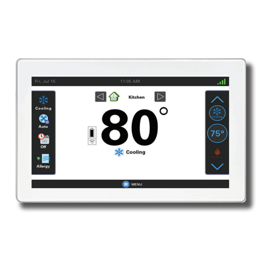
SC360 System Controller /
UX360 Smart Thermostat
With Link technology
ALL phases of this installation must comply with NATIONAL, STATE AND LOCAL CODES.
IMPORTANT - Proper application is critical when installing zoning systems. Not done correctly,
the HVAC and zoning system will not provide the expected comfort. Reference application
bulletins CNT-APG003-EN/Trane and CNT-APG004-EN/AS for detailed information on Zoning
Application.
IMPORTANT - This Document is customer property and is to remain with this unit. Please return to
service information pack upon completion of work.
These instructions do not cover all variations in systems or provide for every possible contingency to
be met in connection with the installation. Should further information be desired or should particular
problems arise which are not covered sufficiently for the purchaser's purposes, the matter should be
referred to your installing dealer or local distributor.
Zoning Installation Guide
Model
ZZON2PNLA200ZA
TM
18-HD99D1-1A-EN
Advertisement
Chapters
Table of Contents

Subscribe to Our Youtube Channel
Summary of Contents for Link ZZON2PNLA200ZA
- Page 1 Zoning Installation Guide Model ZZON2PNLA200ZA With Link technology ALL phases of this installation must comply with NATIONAL, STATE AND LOCAL CODES. IMPORTANT - Proper application is critical when installing zoning systems. Not done correctly, the HVAC and zoning system will not provide the expected comfort. Reference application bulletins CNT-APG003-EN/Trane and CNT-APG004-EN/AS for detailed information on Zoning Application.
-
Page 2: Table Of Contents
2. Zoning Overview ..........2 9. Zone 1 Sensor Setup ........28 3. General Information ........3 10. Sensor Assignment ........29 4. Link Zoning Preparation and Mounting ..4 11. Zoning Airflow Test ........33 5. Zoning Components ........5 12. Zoning Settings and Parameters ..... 37 6. Pre-configuration zoning checklist .. -
Page 3: General Information
Zone Panel is connected and discovered on • Zone Kit (ZZON2KITA200ZAA, contains a the system bus. Panel and a Large Distribution Board) • Zone Panel (ZZON2PNLA200ZA, Panel only, no Distribution Board) Sensor Accessories: • Wired Remote Indoor Sensor • Small (4x) Distribution Board... -
Page 4: Link Zoning Preparation And Mounting
Hole Hole Wire Strain Wire Strain Relief Relief Mounting Hole Follow the below steps to mount the Link Zoning Controller: 1/8” for screw DRILL HOLES into studs 1. Mounting to studs: Drill 1/8” pilot holes in the four locations marked. -
Page 5: Zoning Components
SC360 System Controller / UX360 Smart Thermostat Link system Communication bus connections Indoor temperature Power open / thermistors power close ZZSENSAL0400A dampers terminal inputs terminal outputs 5. Zoning Components 5.1 Label the wires: IMPORTANT: Be careful to provide plenty of Zoning requires a lot of wires. - Page 6 Installation Guide 5.2 Damper Wiring/System Notes: 5.3 Low Voltage Wire Connectors: Zone Dampers Link mode uses simple connectors for low voltage connections. These connections are color coded Terminal Description Color Used which makes the installation easier and quicker. Common Wire Colors...
- Page 7 SC360 System Controller / UX360 Smart Thermostat 5.4 Damper Wire Connectors: 5.5 Duct Dampers: The damper connectors are push-pin connectors. • Each Link Zone panel can support up to three Follow the below instructions to ensure proper zones. attachments/removal of wires: •...
- Page 8 Installation Guide 5.6 Wired Zone Sensors: 5.7 Component Wiring: Control wiring is easy for installations and that The right side of the zone panel is for wired only require a single transformer. The indoor thermistors: unit transformer will power and control all ZZSENSAL0400AA Wired sensors can be components.
- Page 9 • Furnaces will require the installation of the The 8X distribution board provides eight 50VA transformer when incorporating an connection points for Link communication and the electronic air cleaner. 24-volt power source. The Link control components (system controller, The bottom of the distribution board has two...
- Page 10 Most smaller zone systems will not require a Evaluate the Quantity and Total VA for each secondary transformer. possible components in the system. This table shows the transformer loads in a Link The Total System VA is based on worst-case communicating system; showing furnace and air conditions.
- Page 11 SC360 System Controller / UX360 Smart Thermostat 5.11 Furnace Transformer Sizing: Evaluate the Quantity and Total VA for each Evaluate the quantity and total VA for each possible components in the system. possible components in the system. The Total System VA is based on worst-case The Total System VA is based on worst-case conditions.
- Page 12 Installation Guide TAMX Zoned System * = The 4X Distribution Borad may be used when ACCE is not applied. Minimal Zoned 2 Stage Furnace System Can be 2 or 3 zone dampers per zone 18-HD99D1-1A-EN...
-
Page 13: Pre-Configuration Zoning Checklist
2 Stage Furnace Zoned System where the loads require an external transformer Pre-configuration Zoning Checklist • All Link system components have CAN harness connections. Ensure all pieces of the system are connected and powered. • Ensure all zone panels, dampers, and wired sensors are wired correctly to the intended zones. -
Page 14: Trane/As Diagnostics Mobile App
Installation Guide Trane or American Standard Diagnostics Mobile App 7.1 Download the App: Trane Diagnostics App For ease of installation, zoning can also be configured and tested from the Trane or American Standard Diagnostics Mobile App. Follow below steps to download the App: 1. - Page 15 SC360 System Controller / UX360 Smart Thermostat 7.2 LOGIN to the App: 2. If you do not have ComfortSite access, contact 1. Use your ComfortSite username and your dealer admin or password to log in to the app. support@comfortsite.com for help. 18-HD99D1-1A-EN...
- Page 16 Installation Guide 7.3 Connecting to a Link System: 4. Select “Next” for setup assistant. 1. Enable connectivity on the homeowner’s Trane Link Smart Thermostat or American Standard Smart Thermostat. NOTE: This action may not be required for new system installation.
- Page 17 SC360 System Controller / UX360 Smart Thermostat 7.4 Zoning Configuration: Access Zoning Configuration by pressing “Zoning” 2. Select dampers automatically or manually. from the Configuration menu. 3. Select “Run Auto Zone Sizing”. Follow the same commissioning steps in the app that you would from the thermostat: NOTE: Automatic Zone Size Mode is preferred.
-
Page 18: Link Zoning Commissioning
If this toggle is turned off after zoning has been configured, then Link will run the system in single-zone mode (see the zone priority segment for single-zone mode details). - Page 19 Link will auto-detect the zone panels that are wired into the communicating bus and auto- discover zone panel numbers. Link will auto-discover based on a first come / first serve basis. The first zone panel that responds to a Link communication message is Zone Panel 1.
-
Page 20: Zone Panel 2
“Renumber Zone Panels” button before proceeding with zoning configuration. • Link will ask if you wish to renumber zone panels. Confirm by pressing the blue button to “Switch Zone Panels” or select the option for “No Change”. -
Page 21: Dampers
SC360 System Controller / UX360 Smart Thermostat 8.4 Damper Selection: • If current is sensed, the circuit is complete, and Link will auto-enable that zone as having Auto Detect Dampers: a damper. For Zone systems, Select “Auto Detect Installed •... - Page 22 8.5 Zone Sizing & Auto Zone Sizing: Selecting a lower static of 0.7 or 0.8 will calculate zone sizes for lower air flow velocity Auto zone sizing is required with Link zoning. rates and quieter operation. Press “Zone Sizing” button to proceed to with Individual zone sizes and total system size will zoning configuration and auto Zone Sizing.
- Page 23 SC360 System Controller / UX360 Smart Thermostat Total System Size is the sum of all the individual When an outdoor unit is detected, Link will use the outdoor unit for the baseline airflow. All airflow zones and is influenced by the air noise-capacity percentage calculations are based on the outdoor reduction sliders.
- Page 24 Installation Guide 8.6 Zone Priority: Link will not enable zoning if auto zone sizing calculates a total system size of less than 100%. In Each zone must have a zone priority. The priority these instances, evaluate duct restrictions and make sets the level of importance for the zone.
- Page 25 Link will look to medium-priority zones for sensor control. If there are no medium-priority zones with functional sensors, Link will look to low- priority zones for system control. • If there are multiple reporting sensors that fall within the priority grouping noted above, Link will evaluate zone size.
- Page 26 Installation Guide 8.7 Air Noise-Capacity Reduction: The Air Noise - Capacity Reduction slider is found in the configuration menu and zone airflow test mode screens. The slider defaults to 100% and the zone size will match the Last Auto Zone Size. If auto zone sizing populates a zone size that is significantly larger than the duct design, the noise slider can be moved to reduce this individual zone size...
-
Page 27: Total System Va
If a 4-zone system has a basement zone that Zone Name never calls for capacity through the summer season, then Link will be learning the dynamics Defaults to the zone number. Press the Zone of a 3-zone system, and learned zone sizes will Name field to modify the zone name. -
Page 28: Zone 1 Sensor Setup
Installation Guide Zone 1 Sensor Setup Navigate to Zone 1 Sensor Selection: Menu > Service > Enter Technician Access > Proceed > Configuration > Climate Control On the Climate Control screen, scroll down to the Sensor Priority Section. Zone 1 Primary Sensor • The default primary sensor is the Smart Thermostat. • To make a change, select Zone 1 Primary Sensor. -
Page 29: Sensor Assignment
SC360 System Controller / UX360 Smart Thermostat 10. Sensor Assignment 10.1 Indoor Sensor Setup: Link will automatically transition to the sensor setup screen when zone configuration is After Zoning Configuration is complete need to complete. The sensor setup screen can also be assign the sensors to the individual zones. - Page 30 (open / shorted condition). Since wired sensors are physically connected to a zone, Link will only provide an option to assign the sensor to the zone its connected to (or unassign the sensor if needed).
- Page 31 Enable or disable temperature and humidity for each sensor as desired. Link will allow up to four sensors to be averaged within each zone. The system controller (SC360) can also be used as a zone sensor ONLY if it’s installed within the zone that is being controlled.
- Page 32 If a zone only has one wireless sensor assigned and the wireless sensor fails (batteries are weak), then Link will enter single zone mode. All dampers will open, and Link will control temperature based on zone priority and zone size. In this example, if the wireless sensor fails, zone 1 still has three sensors to control temperature and comfort.
-
Page 33: Zoning Airflow Test
SC360 System Controller / UX360 Smart Thermostat 11. Zoning Airflow Test 11.1 Zoning Airflow Test: Adjusted System Size reflects the updates to system size as the “air noise - capacity reduction” Once zoning configuration is complete and sliders are moved. This will show the difference sensors have been assigned, it is recommended in Total &... - Page 34 The dampers to all other zones should be closed Link will take the following actions when this test and there should be no airflow to any other zone. is initiated, and the blower is started: Repeating this for each zone confirms the •...
- Page 35 SC360 System Controller / UX360 Smart Thermostat • Evaluate air delivery rate into each zone. This Run the airflow test with both zones calling to obtain the typical max airflow into this zone. test verifies there is enough throw at max zone airflow and ensures the velocity rates will not This image is representative of all zones being cause a noise complaint.
- Page 36 Installation Guide Lowering the slider will reduce the airflow and capacity to the zone; this may cause excess air issues. Be cautious with marginal duct systems; reducing the slider could cause the total zone size to drop below 100% in auto mode (not allowed). Lowering airflow will also reduce the capacity to the zone.
-
Page 37: Zoning Settings And Parameters
SC360 System Controller / UX360 Smart Thermostat 12. Zoning Settings and Parameters Menu Item Options [Default] Description Toggle ON (green) to enable zoning. Automatically enabled, set to ON (green), when Zoning Enable Zoning Disabled/[Enabled] Configuration is entered. Toggle OFF to disabled zoning. Target Static Pressure [0.9] inch WC Static pressure can be set from 0. - Page 38 Installation Guide Manual Zone Size Mode: Sum of the zones’ Last Auto Zone Sizes. Displayed at Total Auto Zone Size 0.9” WC. Total Available Zone Sum of the zones’ Available Zone Sizes. Displayed at Size the current Target Static Pressure setting. Total System Size Sum of the Manual zone sizes.
-
Page 39: Zone Panel Replacement
Set the new panel and land the wires for the zone dampers and wired sensors; then plug the Link communicating connectors on the new panel. Link will recognize a new panel online and will automatically replace the old panel that is offline. The zone names, priorities, sizes, and sensors are automatically reassigned to their appropriate zones. - Page 40 About Trane and American Standard Heating and Air Conditioning Trane and American Standard create comfortable, energy efficient indoor environments for residential applications. For more information, please visit www.trane.com or www.americanstandardair.com The manufacturer has a policy of continuous data improvement and it reserves the right to change design and specifications without notice. We are committed to using environmentally conscious print practices.
Need help?
Do you have a question about the ZZON2PNLA200ZA and is the answer not in the manual?
Questions and answers