Table of Contents
Advertisement
Available languages
Available languages
Quick Links
Advertisement
Table of Contents

Summary of Contents for Vigor VS-400
- Page 1 MANUALE DI ISTRUZIONI TAGLIATRONCHI cod. 45078-40 VS-400 art.
- Page 2 45078-40 TRONCARAMI VS-400 art.
- Page 3 Gentile Cliente, desideriamo ringraziarla per aver scelto un prodotto della gamma VIGOR, che ci auguriamo sia all altezza delle Sue aspettative. Le ricordiamo, inoltre, che il prodotto da Lei acquistato mira a soddisfare I hobbista esigente nonostante non sia finalizzato ad un uso in campo professionale.
- Page 4 Leggere con attenzione e conservare le istruzioni contenute nel presente manuale. ATTENZIONE! Prima di effettuare qualsiasi operazione sull’unità, leggere con attenzione questo manuale e conservarlo accuratamente per riferimenti futuri. AVVERTENZE E PRECAUZIONI DI SICUREZZA CAPIRE LA MACCHINA Leggere e comprendere il manuale d'uso e le etichette apposte sulla taglierina. Imparare a conoscere le sue applicazioni e i suoi limiti, nonché...
- Page 5 L'uso improprio di prolunghe può causare un funzionamento inefficiente della taglierina, con conseguente surriscaldamento. Assicurarsi che la sezione della prolunga sia sufficiente a consentire un flusso di corrente sufficiente al motore. Evitare l'uso di collegamenti liberi e non adeguatamente isolati. I collegamenti devono essere realizzati con materiale protetto adatto all'uso esterno.
-
Page 6: Rischi Residui
SCOLLEGARE L'ALIMENTAZIONE Scollegare la spina quando non è in uso, prima di effettuare regolazioni, sostituire parti, pulire o lavorare sulla troncatrice; consultare il manuale tecnico prima di effettuare interventi di manutenzione. Rischio di taglio: Non inserire MAI le dita/la mano nell'apertura della protezione mobile! Non mettere MAI le dita/la mano nello spazio tra la protezione fissa e quella mobile! Avvertenza Pericolo di sollevamento! Per spostare la macchina sono necessarie due... - Page 7 PRATICHE DI LAVORO SICURE È essenziale che tutti gli operatori Leggere e comprendere completamente il rapporto di valutazione dei rischi. A Avere una formazione adeguata sull'uso, la regolazione e il funzionamento della macchina; B siano istruiti sui fattori che influenzano l'esposizione al rumore, ad es: - Lama progettata per ridurre il rumore emesso;...
-
Page 8: Uso Previsto
mentre la macchina è in funzione, tranne che per mezzo di un bastone di spinta; S Assicurarsi che le protezioni e gli altri dispositivi di sicurezza necessari al funzionamento della macchina siano in posizione, in buono stato di funzionamento e correttamente mantenuti. -
Page 9: Dati Tecnici
DATI TECNICI CODICE ARTICOLO 45078-40 MOTORE 230V~50Hz 2000W S6 40% IP54 Ø30-Ø135 mm CAPACITA’ DI TAGLIO Length 70~1500 mm LAMA Ø405x30x3.2 mm x32T PESO 39 kg / 42 kg REQUISITI ELETTRICI Con motore a 230 Volt~50Hz, la troncatrice deve essere collegata alla tensione standard di 230V±10%/50Hz. -
Page 10: Schema Elettrico
La temperatura dell'aria ambiente non deve essere inferiore a -15 °C per la macchina. Il motore è idoneo al funzionamento con una tensione di alimentazione con un HVF non superiore a 0,02. RUMORE LwA=108 dB LpA=98 dB alla postazione di lavoro Incertezza K=4dB Misurazione effettuata in conformità... -
Page 11: Componenti Principali
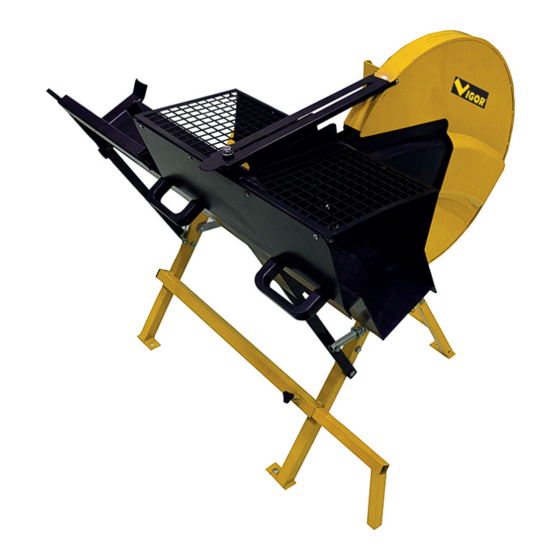
COMPONENTI PRINCIPALI Protezione del legno Morsa per legno Tavolo da lavoro Prolunga del tavolo Catena Gamba di supporto 7. (8) Supporto Interruttore Protezione esterna della lama Motore Piastra di connessione... - Page 12 ASSEMBLAGGIO DISIMBALLAGGIO Pericolo! Pericolo generato da parti mancanti! Per evitare un avvio accidentale che potrebbe causare gravi lesioni personali, assemblare tutte le parti della macchina prima di collegarla all'alimentazione. La macchina non deve mai essere collegata all'alimentazione quando si assemblano parti, si effettuano regolazioni o si installa.
- Page 13 D. Flangia interna E. Flangia esterna C. Supporto scorrevole 1 pz. 1 pezzo 1 pezzo Coprilama interno 2 pezzi G. Lama 1 pz Parti Coperchio fissaggio, molla e esterno della lama chiavi 1 pz...
-
Page 14: Collegamento Alla Rete Elettrica
J. Supporto esteso 1 pz Protezione inferiore Maniglie coprilama esterno N. Tavolo da lavoro manopola Piastra allungato bloccaggio protezione bullone e parte in piano di lavoro plastica Nota: installare la macchina utilizzando i bulloni di fondazione M8 in corrispondenza dei quattro fori di fondazione sulla superficie piana. COLLEGAMENTO ALLA RETE ELETTRICA Pericolo! Alta tensione Utilizzare la macchina solo con una fonte di alimentazione conforme ai seguenti... - Page 15 ASSEMBLAGGIO Collegare la gamba di supporto A e la gamba di supporto B allineando i fori sulle piastre collegamento a sinistra e a destra e utilizzare 2 bulloni (M8x40), 4 rondelle piatte (Ø8) e 2 dadi di bloccaggio (M8) per fissare insieme queste due parti.
- Page 16 Assemblare il coprilama esterno al supporto del motore come mostrato in figura e fissarlo con 4 rondelle piatte (Ø8) e 4 dadi di bloccaggio (M8).
- Page 17 Montaggio della lama Come prima cosa, inserire la flangia interna nel mandrino del motore, quindi inserire la lama e la flangia esterna. Infine, serrare la flangia esterna con una rondella grande (Ø30x30) e un bullone (M10) a turno. Protezione inferiore Collegare la protezione inferiore coprilama...
- Page 18 Collegare il coprilama interno e il tavolo di lavoro inserendo 4 bulloni (6x15) nel foro della piastra del tavolo di lavoro. Quindi serrarli con 4 rondelle piatte (Ø6) e 4 dadi di bloccaggio (M6).
- Page 19 Collegare il tavolo da lavoro allungato, la parte di protezione in plastica al tavolo da lavoro principale con 2 bulloni (M6x12) e 2 rondelle come in figura. Sollevare il tavolo da lavoro con il coprilama interno assemblato verso l'interno del...
- Page 20 coprilama esterno. Collegare il tavolo da lavoro alla gamba di supporto A del lato destro e sinistro serrando 2 bulloni (M8x50), 2 rondelle piane (Ø8) e 2 dadi di bloccaggio (M8) come in figura. Spingere il tubo di guida della molla di ritorno verso il foro della sede della molla, quindi inserire la rondella nella barra di protezione e inserire il perno nel foro del tubo di guida per il bloccaggio, come in figura.
- Page 21 Fissare la piccola protezione interna mobile al coprilama esterno inserendola nel bullone M6 nella parte inferiore del coprilama esterno. Quindi serrare con 1 dado di bloccaggio (M6). Collegare la gamba di supporto e la gamba del tavolo da lavoro con la catena mediante bullone (M6x25), rondella (Ø...
-
Page 25: Funzionamento
FUNZIONAMENTO Prima di utilizzare la macchina, osservare le seguenti informazioni sulla sicurezza! Seguire anche le istruzioni di sicurezza riportate all'inizio del presente manuale! Pericolo generato da difetti della macchina! NOTA: Prima di utilizzare la macchina, fissare i 4 fori con i bulloni (M8X20) sul fondo del supporto. - Page 26 catturata dai componenti in rotazione (non indossare cravatte o indumenti larghi; contenere i capelli lunghi con una retina). Rischio di lesioni personali e di schiacciamento a causa di parti in movimento! Non utilizzare la macchina senza le protezioni installate. Mantenere una distanza sufficiente dai componenti in movimento quando si utilizza l'utensile elettrico.
- Page 27 Riportare completamente il piano di lavoro nella posizione di partenza. Nota: Se il tronco non è stato completamente separato, girarlo e ripetere l'operazione di taglio dal lato opposto (taglio inverso). Rimuovere il pezzo tagliato dalla roccia di alimentazione - eseguire il taglio successivo...
- Page 28 Pericolo! Subito dopo il taglio la lama può essere molto calda - pericolo di ustione! Lasciare raffreddare la lama calda. Non pulire la lama con liquidi combustibili. Indossare guanti durante la sostituzione delle lame. Pericolo! Utilizzare solo lame conformi alle specifiche tecniche e alla norma EN 847-1:2005 - parti di lame non adatte o danneggiate possono essere scagliate via in modo esplosivo.
-
Page 29: Cura E Manutenzione
Nota: installare sempre il supporto di trasporto prima di trasportare il tagliatronchi. Ogni 50 ore di funzionamento Controllare tutti i collegamenti a vite, se necessario serrarli (il bilanciere e l'arresto del bilanciere devono rimanere mobili). Controllare che la lama sia ben salda, usurata e affilata. Rimuovere eventuali depositi accumulati all'interno del coperchio della lama. - Page 30 Istruzioni per lo smaltimento del prodotto. Il disegno del bidone con una barratura (eventualmente riportato anche sull’apparecchio stesso) indica che si tratta di AEE (apparecchio elettrico ed elettronico) e che pertanto nel caso di smaltimento lo stesso dovrà essere depositato presso gli appositi contenitori di RAEE (rifiuti di apparecchiature elettriche ed elettroniche).
- Page 31 ai sensi dell’art. 3 del Codice del Consumo, “le persone fisiche che agiscono per scopi estranei all’attività imprenditoriale, commerciale, artigianale o professionale eventualmente svolta”) per tutti i prodotti acquistati con normale ricevuta/scontrino fiscale; la GARANZIA PER VIZI, prevista dall’articolo 1495 del Codice Civile, della durata di 12 MESI.
- Page 32 Read the instructions included in this manual carefully. WARNING! Before carrying out any operation on the unit, read this manual carefully and keep it for future reference. SAFETY WARNINGS & CAUTIONS UNDERSTAND YOUR CUTTER Read and understand the owner’s manual and labels affixed to the cutter. Learn its application and limitations as well as the specific potential hazards peculiar to it.
- Page 33 AVOID ELECTRICAL SHOCK Check that the electric circuit is adequately protected and that it corresponds with the power, voltage and frequency of the motor. Check that there is a ground connection, and a regulation differential switch upstream. Ground the cutter. Prevent body contact with grounded surfaces: pipes, radiators, ranges, and refrigerator enclosures.
-
Page 34: Residual Risks
person at each end of the machine. MAINTAIN YOUR CUTTER WITH CARE Keep the log saw clean for best and safest performance. MAKE THE WORKSHOP CHILDPROOF Lock the shop. Disconnect master switches. Store the log saw away from children and others not qualified to use it. RESIDUAL RISKS The following risks are inherent to the use of these machines: •... - Page 35 It is essential all operators are: Read and understand the risk assessment report completely first. A Adequately trained in the use, adjustment and operation of the machine; B Instructed in factors that influence exposure to noise e.g.: • sawblade designed to reduce the emitted noise; •...
-
Page 36: Application Conditions
S Ensure that guards and other safety devices necessary machine operation are in position, in good working order and properly maintained. T Warning- Max. slope 5% for the installation surface. WARNING Through poor conditions of the electrical MAINS, shortly voltage drops can appear when starting the EQUIPMENT. -
Page 37: Technical Data
TECHNICAL DATA ITEM CODE 45078-40 MOTOR POWER 230V~50Hz 2000W S6 40% IP54 Ø30-Ø135 mm CUTTER CAPACITY Length 70~1500 mm BLADE DIAMETER Ø405x30x3.2 mm x32T WEIGHT 39 kg / 42 kg ELECTRICAL REQUIREMENTS With 230 Volt~50Hz motor, the log saw should be connected to standard 230V±10%/50Hz. -
Page 38: Wiring Diagram
The motor is suitable for operation on a supply voltage having a HVF not exceeding 0,02. NOISE LwA=108 dB L pA =98 dB at workstation Associated K=4dB Measurement made in accordance with EN ISO 3746:1995 The figures quoted are emission levels and are not necessarily safe working levels. Whilst there is a correlation between the emission and exposure levels, this cannot be used reliably to determine whether or not further precautions are required. -
Page 39: Main Components
MAIN COMPONENTS Wood protection guard Wood vice Working table Table extension Chain Support leg 7. (8) Stand Switch 10. Blade outer guard 11. Motor 12. Connection plate... -
Page 40: Loose Parts List
ASSEMBLY UNPACKING Danger! Hazard generated by missing parts! To prevent accidental starting that could cause possible serious personal injury, assemble all parts to your machine before connecting it to power supply. This machine should never be connected to power supply when you are assembling parts, making adjustments, installing. - Page 41 D. Inner flange 1pc E. Outer flange 1pc C. Sliding support 1pc Inner blade G. Blade 1pc cover 2pcs I. Parts for fastening, Outer blade spring and spanners cover 1pc...
-
Page 42: Mains Connection
J. Extended holder O. Lower guard for outer blade cover M. Handles and K. Working table N. Extended work locking knob protective plate table with bolt and plastic part Note: Install the machine by using of foundation bolts M8 acc. to the four foundation holes on the level concrete surface. - Page 43 ASSEMBLY Connect support leg A & support leg B by aligning the holes on the two connecting plates on left &right side and use 2 bolts(M8x40),4 flat washers (Ø8) and 2 locking nuts (M8) to fasten these two parts together.
- Page 44 Assemble the outer blade cover to the motor support stand as shown in the picture and fix by 4 flat washers ((Ø8) and 4 locking nuts (M8).
- Page 45 Assembling the saw blade Firstly, put the inner flange into the motor spindle, and then put on blade and the outer flange. Lastly, tighten the outer flange by big washer ( Ø30x30) and bolt ( M10 ) in turn. Lower guard Connect lower guard to the outer blade...
- Page 46 Connect the inner blade cover and the work table by putting 4 bolts (6x15) into the hole on the work table plate. Then tighten them by 4 flat washers (Ø6) and 4 locking nut (M6).
- Page 47 Connect the extend work table, plastic protection part to the main work table with 2 bolts (M6x12), 2 washers as picture. Lift up the work table with assembled inner blade cover towards inside of the outer blade cover. Connect the work table to the support leg A of left and right side by tightening 2 bolts (M8x50), 2 flat washers (Ø8) and 2 locking nut (M8) as picture.
- Page 48 Push the return spring guiding pipe toward the hole of spring seat and then put washer into the guard bar and put the pin into the hole of guiding pipe for locking as picture.
- Page 49 Fix the small movable inner protection cover to the outer blade cover by putting it into the bolt M6 at the bottom of the outer blade cover. Then tighten it by 1 locking nut (M6). Connect the supporting leg and the work table leg with chain by coach bolt (M6x25), washer (Ø...
-
Page 53: Operation
OPERATION Please take note of the following safety information before operating the machine! Also follow the safety instructions given at the beginning of this manual! Hazard generated by machine defects! NOTE: Before Using the Machine, Please fix the 4 holes with Bolts (M8X20) at the Bottom of the Stand Before starting work, check to see that the following are in proper working order: Saw blade (firmly mounted? Undamaged? Sharp? Sufficient distance to other parts?) - Page 54 hand. Always use the feed rocker to feed the logs to be cut. Always hold the feed rockers with both hands at its handle. Assume proper operating position: • At the front of the saw; • In the front of the saw; •...
- Page 55 IMPORTANT: Pull the power plug! Allow the saw blade to cool before you change it. Do not use inflammable liquids to clean the saw blade. Always wear gloves when handling saw blades. Steps to change blade: Discharge the lower guard from the outer blade cover. Undo the flange screw by turning it counter–clockwise.
-
Page 56: Saw Storage
Danger! Directly after cutting the saw blade can be very hot – burning hazard! Let a hot saw blade cool down. Do not clean the saw blade with combustible liquids. Wear gloves when changing blades. Danger! Use only saw blades conforming to the technical specifications and EN 847-1:2005 –... -
Page 57: Care And Maintenance
remain movable). Check saw blade for firm seat, wear and sharpness. Remove any deposits that may have built up inside the saw blade cover. CARE AND MAINTENANCE Danger! Prior to all servicing: Switch machine OFF; Wait for saw blade to complete stop; Unplug power cable;... - Page 58 Instructions for disposal The bin symbol (on the packaging and/or product) indicates that the article is classified as EEE (electrical and electronic equipment), and must therefore be disposed of in the appropriate recycling receptacles of WEEE (waste electrical and electronic equipment).
- Page 59 acting for purposes which are outside his trade, business or profession”) for all the products purchased with normal sales receipt; the WARRANTY FOR DEFECTS, set by article 1495 of Civil Code, that lasts 12 MONTHS. This guarantee is applied to all professional operators, that means the final users that are VAT-registered (societies made of persons or capital, sole proprietor firms, craft businesses, independent professionals, etc.) that use the product for professional purpose and that purchase the product with the sales receipt.
-
Page 60: Dichiarazione Di Conformita' Ue
L’azienda VIGLIETTA MATTEO S.p.A, con sede in Fossano, via Torino 55 (CN) Italia, dichiara sotto la propria esclusiva responsabilità di fabbricante che il prodotto TAGLIATRONCHI art. VS-400, cod. 45078-40, Marca VIGOR, Modello LS-400, è conforme alle seguenti pertinenti normative di armonizzazione dell’Unione: 2006/42/CE –... - Page 62 Made in China Lot no. 2211R00342 Importato da Viglietta Matteo S.p.A. Via Torino 55 - 12045 Fossano (CN) Italy Riservato il diritto di apportare modifiche tecniche.