Table of Contents
Advertisement
Quick Links
INSTALLATION, OPERATION & MAINTENANCE INSTRUCTIONS
ASD SERIES
PNEUMATIC ACTUATORS
SPRING-DIAPHRAGM ROTARY ACTUATORS
This instruction manual includes installation, operation
and maintenance information for FNW Pneumatic Spring-
Diaphragm Actuators. Please read these instructions
carefully and save them for future reference. It is important
that only properly trained personnel disassemble or
assemble the actuator.
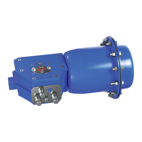
GENERAL PRODUCT DESCRIPTION
The FNW Spring-Diaphragm Actuator is specifically
designed for the safe and reliable operation of quarter turn
valves under minimal media supply pressure. The design
separates the supply media chamber from the spring sets,
allowing for usage of unfiltered air, gas, water or mineral-
based hydraulic fluid. The housing is constructed from
ductile iron and carbon steel castings coated in a
1. CAUTION/IMPORTANT SAFETY WARNINGS
• Only authorized and properly trained personnel should perform installation and maintenance of the actuator. Proper PPE
should be used as required.
• Before working on a FNW Spring-Diaphragm Actuator, please note that all fasteners and screw threads are metric except
for the JB mount screw threads which are imperial.
• For correct and safe operation, pneumatic actuators must be sized adequately and with sufficient safety margin of torque
output for the correct operating conditions of the valve or application.
• Operating the actuator beyond its stated maximum operating limits of temperature, pressure or recommended operating media
can cause damage to the internal components, actuator housing or result in personal safety risks involving death or injury.
• Before carrying out any installation, repair or maintenance on the actuator, make sure that the electrical connections have
been safely isolated, removed or disconnected by authorized personnel. All pneumatic supply lines should be shut-off,
removed and completely bled. The actuator must not be pressurized at any time during installation, repair or maintenance
unless otherwise noted in the instructions, as injury may result.
• Never put any part of your body in the opening or port of the controlled valve or device.
• Special attention and precautions should be observed due to the stored energy contained in the spring cartridge. Do not
attempt to disassemble the spring cartridge. Disassembly may result in damage or personal injury. If maintenance is required for
the spring cartridge, the entire actuator should be returned to FNW for assistance. Please contact FNW for additional information.
• When servicing a valve actuator assembly, the best practice is to remove the entire assembly from service. If the actuator
is removed from the valve, it should be remounted on the same valve after servicing is completed. The actuator must be
readjusted for proper open and close position each time it is remounted.
• Before installing the valve and actuator, be sure that the indicator pointer (2) on top of the actuator and the indicator plate
(4) are correctly indicating the valve position. Failure to assemble the valve and actuator to the correct valve position could
result in damage or personal injury.
• Do not lift actuators using the 1/4" NPT in the diaphragm cover. Actuators should be handled using lifting straps as seen in
Section 5.
• Use only FNW-recommended spare parts for maintenance.
• To ensure safety and to maintain warranty, never modify the actuator in any way not indicated in this manual without prior
approval from FNW.
FNW.COM
UV-resistant polyester powder coating for exceptional
corrosion resistance in the field. The independent media
chamber is also equipped with a standard LNBR diaphragm
reinforced with a special compound polyamine fabric.
Optional diaphragm materials allow for working temperature
ranges as low as -40°C (-40°F) or as high as 170°C (338°F).
We reserve the right to modify or improve the designs or
1
specifications of our products at any time without notice.
Advertisement
Table of Contents

Related Manuals for FNW ASD Series

Summary of Contents for FNW ASD Series
- Page 1 • Only authorized and properly trained personnel should perform installation and maintenance of the actuator. Proper PPE should be used as required. • Before working on a FNW Spring-Diaphragm Actuator, please note that all fasteners and screw threads are metric except for the JB mount screw threads which are imperial.
-
Page 2: Operating Conditions
INSTALLATION, OPERATION & MAINTENANCE INSTRUCTIONS ASD SERIES PNEUMATIC ACTUATORS SPRING-DIAPHRAGM ROTARY ACTUATORS 2. STORAGE ATTENTION: If the actuators are not destined for immediate use, the following storage precautions should be taken: • Ensure the actuators are completely dry and water free. -
Page 3: Operating Media
INSTALLATION, OPERATION & MAINTENANCE INSTRUCTIONS ASD SERIES PNEUMATIC ACTUATORS SPRING-DIAPHRAGM ROTARY ACTUATORS Operating Media Air (max particle size 50 µm), gas, water or mineral-based hydraulic fluid Air Supply Pressure Minimum operating pressure: 1 bar (15 psi) Maximum operating pressure: 7 bar (100 psi) Operating Temperature Standard: -25°C to 70°C (-13°F to 158°F) -
Page 4: Lifting Straps
INSTALLATION, OPERATION & MAINTENANCE INSTRUCTIONS ASD SERIES PNEUMATIC ACTUATORS SPRING-DIAPHRAGM ROTARY ACTUATORS 5. HANDLING Lifting Straps Lifting straps should be used to safely handle the actuator as shown in the figure to the right. Approximate weights can be found in the below table. Lifting straps should be in good condition and of sufficient size and material to handle the load. - Page 5 INSTALLATION, OPERATION & MAINTENANCE INSTRUCTIONS ASD SERIES PNEUMATIC ACTUATORS SPRING-DIAPHRAGM ROTARY ACTUATORS • Mount the accessories, such as a limit switch box or valve positioner, to the actuator following NAMUR (VDI/VDE 3845) standards. The accessory can be directly mounted on the cover (8) of the actuator in spring-to-close mode. In spring-to-open mode, the accessory can be directly mounted on the driver housing (13) of the actuator.
-
Page 6: General Maintenance
10. GENERAL MAINTENANCE Under normal operating conditions, the FNW Spring-Diaphragm Actuator requires only periodic checks to ensure proper adjustment. Standard replacement items generally consist of bearings and diaphragms. These are numbered 9, 10, 25, 34 and 37 in the BOM. -
Page 7: Replacing The Diaphragm
If tension still exists on the hex head screws, then the spring package is not properly contained. Stop disassembly, retighten nuts and return the actuator to FNW. If the spring package is intact, continue to remove the nuts (20), spring-washers (21), gaskets (22), and remove the hex head screws (39). -
Page 8: Tool List
Stop disassembly, retighten nuts and return the actuator to FNW. If the spring package is intact, continue to remove the nuts (20), spring-washers (21), gaskets (22), and remove the hex head screws (39). -
Page 9: Actuator Assembly
16.1 INSTALLATION, OPERATION & MAINTENANCE INSTRUCTIONS ASD SERIES PNEUMATIC ACTUATORS (ASD4, ASD5, ASD6) SPRING-DIAPHRAGM ROTARY ACTUATORS 17.1 37.1 37.2 12. ACTUATOR ASSEMBLY CAUTION: To aid assembly, a commercial lubricant which is compatible with the gasket and diaphragm materials can be used. • Press driver arm bearings (9) into the driver housing (13) and cover (8). An arbor press should be used as best practice; however, a vise can be used if care is taken not to damage the bearings or other components. - Page 10 INSTALLATION, OPERATION & MAINTENANCE INSTRUCTIONS ASD SERIES PNEUMATIC ACTUATORS SPRING-DIAPHRAGM ROTARY ACTUATORS 13. PARTS AND MATERIAL LIST Part Name Material Surface Treatment ASD2/3 ASD4/5 ASD6 Snap Ring Stainless Steel 304 Indicator Pointer Stainless Steel 304 Hex Head Cap Screw Stainless Steel 304...
- Page 11 INSTALLATION, OPERATION & MAINTENANCE INSTRUCTIONS ASD SERIES PNEUMATIC ACTUATORS SPRING-DIAPHRAGM ROTARY ACTUATORS Part Name Material Surface Treatment ASD2/3 ASD4/5 ASD6 Cover Carbon Steel Polyester Powder Coated Driver Arm Bearing Stainless Steel w/Acetal Lining Thrust Bearing Nylon Cylindrical Pin Carbon Steel...
-
Page 12: Limited Warranty
A PARTICULAR PURPOSE. In order to file a claim under the terms of this Warranty, a claimant must promptly notify FNW that a product may be defective within 30 days of the suspected failure or defect via the telephone number, mail or website listed below and may be required to submit proof of purchase and/or photographs.
Need help?
Do you have a question about the ASD Series and is the answer not in the manual?
Questions and answers