
Summary of Contents for STELTEC STE-INV-HB5000
- Page 1 Shanghai Steltec Energy Technology CO.,LTD Address:Room J4986, Floor1, NO.185, Moyu Road , Anting Town, Jiading District, Shanghai China www.steltec-ess.com V1.0-2023-03-06...
-
Page 2: Table Of Contents
3.7 Meter/CT Communication Connection Copyright Statement 3.8 RS485 Connection This manual is under the copyright of Steltec Co., Ltd. with all rights 3.9 NTC/RMO/DRY Connection(s) reserved. Please keep the manual properly and operate in strict accor- dance with all safety and operating instructions in this manual. Please do 3.10 WiFi Datalogger Connection... -
Page 3: System Introduction
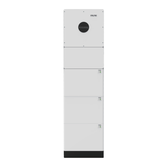
S hanghai S teltec E nergy T ec hnology C O .,LT D 1 Product Introduction 1.1 System introduction STELTEC E-home energy storage system include STE-INV-HB5000/6000 inverter STE-BSG-5220 and system box. STE-INV-HB5000/6000 inverter and STE-BSG- 5220 are our standard products which can be sold independently. System box are designed for the E-home energy storage system and it owns a DC battery breaker(125A) inside and can cover all the cables as you can seen below pictures. -
Page 4: Ste-Inv-Hb5000/6000Information
S hanghai S teltec E nergy T ec hnology C O .,LT D 1.2 STE-INV-HB5000/6000 information Inverter Specification STE-INV-HB50 STE-INV-HB6000 Efficiency Max.Efficiency(PV to Grid) 97.3% Input(PV) Max.Input Voltage 550V Max.Input Current 15/15A Max.Short Circuit Current 20/20A Start Input Voltage MPPT Operating Voltage Range... - Page 5 S hanghai S teltec E nergy T echnology C O .,LT D Tec h n ic al S ec ic a t i n P o w e r N u m b e r B a tte ry B a tte ry B a tte ry B a tte ry B a tte ry...
- Page 6 S hanghai S teltec E nergy T ec hnology C O .,LT D ON/OFF Definition Pin 1 RS485-B (to PCS, reserved) 1. ON Pin 2 RS485-A (to PCS, reserved) For single Battery Module, Long press (more than 3 seconds) ON/OFF button, Normal GND_2 Pin 3 LED will be lighted in the front panel then battery will operate normally.
-
Page 7: System Box Information
S hanghai S teltec E nergy T ec hnology C O .,LT D The following location are not allowed for installation: 1.4 System box information • abitable rooms; • eiling cavities or wall cavities; • n roofs that are not specifically considered suitable; •... -
Page 8: Installation Steps
S hanghai S teltec E nergy T ec hnology C O .,LT D If the E-home is mounted at a wall or at a distance of 300mm from the wall or structure separating it from the habitable space, the distances to other structures or objects must be increased. - Page 9 S hanghai S teltec E nergy T ec hnology C O .,LT D Step 4 Step Fix the mounting plate as ,confirm the position where to drill a hole in the wall. Step Take off the L shape metal and the mounting plate and drill hole on the wall. a depth of about 45mmin the wall for subsequent fixation of the mounting plates.
- Page 10 S hanghai S teltec E nergy T ec hnology C O .,LT D NOTE: Place a cover (paper, foil, etc.) over the battery while drilling into the Step wall to protect it from dust. In addition, at the place of installation, the slope of the ix the system box to the battery using screw M5*8 (from the system box) ground on a horizontal plane may not exceed 3°.
-
Page 11: Electrical Connection
S hanghai S teltec E nergy T ec hnology C O .,LT D 3 Electrical Connection Step Insert the bracket into the mounting plate as below This chapter shows the details connection of ESS inverter. And PV connection is N/A for AC couple inverters. The following illustration only uses the hybrid inverters as an example. -
Page 12: Grounding
S hanghai S teltec E nergy T ec hnology C O .,LT D 3.1 Grounding a.Connect to the ground between inverter and system box using M5 hexagon nuts with flange b.Connect the battery to ground with a small metal plate using screw M4*8(from the system box) as follows and there is a 1.5m GND cable to fix the base Grounding... -
Page 13: Grid/Eps Connection
S hanghai S teltec E nergy T ec hnology C O .,LT D a.Connect the battery power cable in the down side of the breaker in the system box to the upper battery which is the master battery. Connect the battery power cable in the up side of the breaker in the system box to the inverter battery ports. -
Page 14: Pv Connection
S hanghai S teltec E nergy T ec hnology C O .,LT D 3.4 PV Connection Cable Gland Threaded Sleeve Connection Terminal Grid/EPS Connector Structure Positive Connector Limit buckle It is recommended to use outdoor Diameter dedicated cables with multiple 4~6mm copper cores. -
Page 15: Communication Connection
S hanghai S teltec E nergy T ec hnology C O .,LT D inverter only supports the meter: CHNT-DDSU666 meter. Load Grid Load Grid Inverter Side Side DDSU666 Grid Please attention to the Current interchanger (CT) connection. The arrow on the equipped) between meter and Grid. - Page 16 S hanghai S teltec E nergy T ec hnology C O .,LT D DRMs Connectio BMS Connection DRMs is a shortened form for “inverter demand response modes”. It is a compulsory requirements for inverters in Australia. Pin 12345678 Pin 12345678 Function Function DRM1/5...
- Page 17 S hanghai S teltec E nergy T ec hnology C O .,LT D Meter Connection CT Connection CT cable connection overview Pin1 or 3 Pin2 or 4 Inverter Pin5(CT-) Black Pin6(CT+) Connect CT. Refer to the following steps: DDSU666 Inverter Meter Pin1 or Pin3(RS485_A ) Pin24...
-
Page 18: Rs485 Connection
S hanghai S teltec E nergy T ec hnology C O .,LT D 3.8 RS485 Connection 3.9 NTC/RMO/DRY Connection(s) RJ45 Terminal Configuration of RS485 Communication 9-Pins Terminal Configuration of Auxiliary Communication Function Description Function RS485_A RS485_B Description NO1 (Normal Open) Connect RS485. -
Page 19: Wifi Datalogger Connection
S hanghai S teltec E nergy T ec hnology C O .,LT D Unscrew the waterproof cover and loosen the rubber nut on waterproof cover. Connect and tighten the cable between the WIFI datalogger and the external Install the external Antenna. Antenna. -
Page 20: Inverter Working Mode
S hanghai S teltec E nergy T ec hnology C O .,LT D 4 System Operation b) Limited PV power When the PV energy is not enough to cover all the loads, all the PV energy will be used for load, and the insufficient part will be supported by battery. Then still 4.1 Inverter Working Mode insufficient parts will be supported by grid. - Page 21 S hanghai S teltec E nergy T ec hnology C O .,LT D 4.1.2 Feed-in Priority Mode Go to the "Hybrid work mode" menu, and select the "Feed-in priority mode" working mode. Under this mode, the priority of PV energy will be Load > Grid >...
- Page 22 S hanghai S teltec E nergy T ec hnology C O .,LT D 4.1.3 Time-Based Control Mode Go to the "Hybrid work mode" menu, and select the "Time-based Control" working mode. Under this mode, you can control the charging and discharging of the inverter.
- Page 23 S hanghai S teltec E nergy T ec hnology C O .,LT D 4.1.5 Off Grid Mode When the power grid is cut off, the system automatically switches to Off Grid mode.Under off-grid mode, only critical loads are supplied to ensure that important loads continue to work with grid cut-off.Under this mode, the inverter can’t work without the battery.
-
Page 24: Start Up The System
S hanghai S teltec E nergy T ec hnology C O .,LT D 4.2 Start up the System Check and confirm the installation is secure and strong enough and that the system groundingis OK. Then confirm the connections of AC, battery, PV etc. are correct. -
Page 25: Commissioning And Inspection
S hanghai S teltec E nergy T ec hnology C O .,LT D 5 Commissioning and Inspection LED Indicator Status Description PV input is normal. 5.3Commissioning Blink PV input is abnormal. It is necessary to make a complete commissioning of the PV is unavailable. -
Page 26: Led
S hanghai S teltec E nergy T ec hnology C O .,LT D ALARM Grid ALARM Details Code Grid Details COM LED ALARM LED Details Code EPS LED PV normal PV normal WLAN/RS485/DB9/BLE/USB RS485/DB9/BLE/USB No PV No PV Inverter over temperature Inverter over temperature PV over voltage PV over voltage... -
Page 27: App Setting Guide
S hanghai S teltec E nergy T ec hnology C O .,LT D 6.2.3 Local Setting 6.2 App Setting Guide Access Permission Before using the local setting, “SolarHope” APP should access some permissions. ( You need to grant all access rights in all pop-up windows when installing the APP Download “SolarHope”... - Page 28 S hanghai S teltec E nergy T ec hnology C O .,LT D 3. Set parameters of power limit Quick Setting XXXXXXXX Step 1 Click each item to enter the parameters of power limit. 1.Connect to the router. Step 2 Click Next Step 1 Go to Quick Setting page.
- Page 29 S hanghai S teltec E nergy T ec hnology C O .,LT D APP Power Chart 1. Query (Daily) Data The power chart is showed by Day, Month and Year in our APP. For each Go to Chart > Day page. It will show the Daily Production or Consumption Curve in exhibition method, it includes both Production and Consumption.
- Page 30 S hanghai S teltec E nergy T ec hnology C O .,LT D 2. Query (Monthly) Data Day Chart--Consumption Go to Chart > Month page. It will show the Monthly Production or Consumption Curve in this page. You can swipe the screen left and right to switch the graph. Month Chart--Production The above combination day chart shows the load consumption power from three parts: PV generation power (Blue)
- Page 31 S hanghai S teltec E nergy T ec hnology C O .,LT D Query (Yearly) Data Month Chart--Consumption Go to Chart > Year page. It will show the Annually Production or Consumption Curve in this page. You can swipe the screen left and right to switch the graph. Year Chart--Production The above combination month chart shows the load consumption capacity from three parts: The above combination year chart shows the distribution of PV production capacity with three parts:...
- Page 32 S ha ngh ai S te lte c E n e rg y T e chn olo g y C O .,L T D 2. Local Setting Homepage Year Chart--Consumption This page shows the basic information of inverter. Clickto display the warning message. XXXXXXXX XXXXXXXX 19.1kWh...
- Page 33 S hanghai S teltec E nergy T ec hnology C O .,LT D 2. Local Setting Homepage Year Chart--Consumption This page shows the basic information of inverter. Clickto display the warning message. XXXXXXXX XXXXXXXX 19.1kWh 494kWh 19.1kWh 494kWh E-Today E-Total E-Today E-Total Self used mode...
- Page 34 S hanghai S teltec E nergy T ec hnology C O .,LT D Maintenance XXXXXXXX 19.1kWh 494kWh Go to Console E-Today page. And click E-Total Maintenance Self used mode STE-INV-HB4600 2.71kW 405W XXXX-XXXXXXXXXX 2.21kW 0.00W 60.0W Production: 19.1kWh 53.0% 47.0% 10.1kWh Consumed directly: To Grid:...
- Page 35 S hanghai S teltec E nergy T ec hnology C O .,LT D Grid Parameters Console Go to Console > Grid Parameters page. In this page, you can Access Management set or change the parameters of Grid side, as shown in the figure. Go to Console Access Management...
- Page 36 S han gh ai S te lte c E n erg y T e chn o lo gy C O .,L T D How to Autotest? xxxxxxxx Step 1. Go to Grid Parameters > Standard Code page to select the IT (CEI 0-21). Step 2.
-
Page 37: Remote Monitoring
S han gh ai S te lte c E n erg y T e chn o lo gy C O .,L T D 6.3 Remote Monitoring Other Setting Go to Console > Other Setting page. In this page, you can set other setting parameters. 6.3.1 Remote Monitoring Since you have configurated the inverter to router via SolarHope APP in page 51, please use SOLARMAN WEB or APP for remote monitoring of the inverter. - Page 38 S hanghai S teltec E nergy T ec hnology C O .,LT D Troubleshooting 1. If the alarm occurs occasionally, possibly the power grid voltage is abnormal temporarily, and no action is required. Inverter over dc-bias current 2. If the alarm occurs repeatedly, and the inverter fails to generate When the inverter has an exception, its basic common warning and handling methods are shown below.
- Page 39 S hanghai S teltec E nergy T ec hnology C O .,LT D 1. If the alarm occurs occasionally, the inverter can be automatically Internal communication error recovered and no action is required. 1. If the alarm occurs occasionally, the inverter can be automatically 2.
-
Page 40: Removing The Inverter
S hanghai S teltec E nergy T ec hnology C O .,LT D Before removing DC input connector, double check DC input switch is turned WARNING to OFF to avoid inverter damage and personal injury. 1. Check whether the communication cables between EPS, electricity Internal communication loss meter and inverter are well connected and whether the wiring is correct (E-M)
Need help?
Do you have a question about the STE-INV-HB5000 and is the answer not in the manual?
Questions and answers