Table of Contents
Advertisement
Quick Links
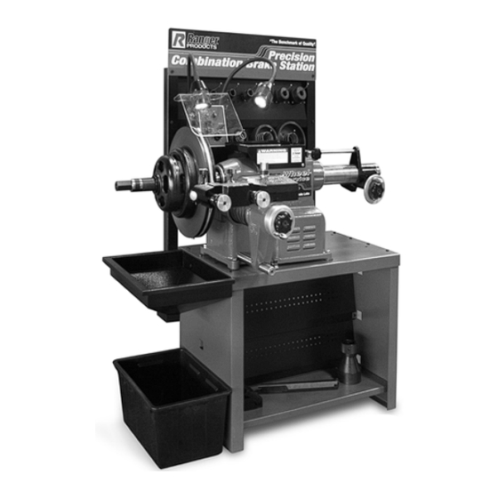
MODELS:
RL-8500
RL-8500XLT
COMBINATION
BRAKE LATHE
SHIPPING DAMAGE CLAIMS
When this equipment is shipped, title passes to the
purchaser upon receipt from the carrier. Consequently,
claims for the material damaged in shipment must be
made by the purchaser against the transportation
company at the time shipment is received.
PLEASE READ THE ENTIRE CONTENTS OF THIS MANUAL PRIOR TO
INSTALLATION AND OPERATION . BY PROCEEDING YOU AGREE THAT
YOU FULLY UNDERSTAND AND COMPREHEND THE FULL CONTENTS OF
THIS MANUAL. FORWARD THIS MANUAL TO ALL OPERATORS. FAILURE TO
OPERATE THIS EQUIPMENT AS DIRECTED MAY CAUSE INJURY OR DEATH.
INSTALLATION AND OPERATION MANUAL
FOR RESURFACING
AUTOMOBILE
AND LIGHT TRUCK DRUMS,
ROTORS
AND FLYWHEELS
Keep this operation manual near the
machine at all times. Make sure that
ALL USERS read this manual.
BE SAFE
Your new Ranger brake lathe was designed and
built with safety in mind. However, your overall
safety can be increased by proper training and
thoughtful operation on the part of the operator. DO
NOT operate or repair this equipment without read-
ing this manual and the important safety instruc-
tions shown inside.
Rev. D 10-01-14
1645 Lemonwood Dr.
Santa Paula, CA. 93060, USA
Tel: 1-805-933-9970
Toll Free 1-800-253-2363
Fax: 1-805-933-9160
www.rangerproducts.com
Advertisement
Table of Contents

Related Manuals for Ranger Products RL-8500

Summary of Contents for Ranger Products RL-8500
- Page 1 YOU FULLY UNDERSTAND AND COMPREHEND THE FULL CONTENTS OF THIS MANUAL. FORWARD THIS MANUAL TO ALL OPERATORS. FAILURE TO OPERATE THIS EQUIPMENT AS DIRECTED MAY CAUSE INJURY OR DEATH. Rev. D 10-01-14 INSTALLATION AND OPERATION MANUAL MODELS: RL-8500 FOR RESURFACING AUTOMOBILE RL-8500XLT AND LIGHT TRUCK DRUMS, COMBINATION...
-
Page 2: Warranty
This warranty is exclusive and in lieu of all other warranties expressed or implied. In no event shall Ranger Products be liable for special, consequential or incidental damages for the breach or delay in performance of the warranty. Ranger Products reserves the right to make design changes or add improvements to its product line without incurring any obligation to make such changes on product sold previously. -
Page 3: Table Of Contents
Do not operate this machine until you read and RL-8500 Features ........7 understand all the dangers, warnings and cautions RL-8500 Specifications . -
Page 4: Owner's Responsibility
DEFINITION OF OWNER’S RESPONSIBILITY HAZARD LEVELS To maintain machine and user safety, the responsibility of the owner is to read and follow these instructions: Identify the hazard levels used in this manual with the following definitions and signal words: Follow all installation instructions. Make sure installation conforms to all applicable Local, State, and Federal Codes, Rules, and Regulations;... -
Page 5: Warning Instructions
Check to make sure assist in helping you process your claim does not make all parts are secure. Ranger Products responsible for collection of claims or replacement of lost or damaged materials. 5. Make sure the rotors/drums/flywheels are clean and mounted properly before operating lathe. -
Page 6: Important Safety Instructions
IMPORTANT SAFETY INSTRUCTIONS ! Before operating the lathe, review the warning information on the lathe and the cautions, warnings and dangers in this manual. Also review the following general safety instructions. PROVIDE ADEQUATE VENTILATION when When using your brake lathe basic safety precautions working on operating internal combustion engines. -
Page 7: Rl-8500 Features
• An independent cross feed motor eliminates the need for plastic or bronze shear gears which are expensive and The Ranger RL-8500 Combination Brake Lathe is intended timely to replace. to resurface disc brake rotors, brake drums and flywheels on passenger cars, medium duty trucks only. -
Page 8: Rl-8500Xlt Features
• The RL-8500XLT maintains accuracy year after year MODEL RL-8500XLT thanks to ruggedly constructed components, like a HEAVY DUTY BRAKE LATHE wwhardened, precision ground spindle that resists grooving and makes boots a thing of the past. The Ranger RL-8500XLT Heavy Duty Combination Brake •... -
Page 9: Location/Rl-8500 Tooling Package
EQUIPMENT LOCATION Proper unit installation is necessary for safe use and efficient operation. Proper installation also helps protect the unit from damage and makes service easier. Always keep this manual nearby. Location Select a location that will provide the operator with enough space to use the equipment in a safe manner. -
Page 11: Assembly View
ASSEMBLY VIEW Item # Description Upper Chip Tray Cross Feed Assembly Twin Cutter Head Plastic Shield Guard Work Light (2) Power Control Box Upper Panel Assembly Tool Tray Spindle Assembly Work Bench Lower Panel Assembly Lower Chip Tray... -
Page 12: Step 1 - Installation
STEP 1 (Installation) 1. Assemble the Bench with Chip Tray as shown below. Tighten all fasteners securely. NOTE: THIS UNIT CAN BE POWERED WITH 110 VOLTS OR 220 VOLTS. THE LATHE IS SHIPPED WITH THE VOLTAGE SELECTOR SWITCH IN THE NEUTRAL POSITION. -
Page 13: Step 2 - Basic Set Up
Arbor with the tick mark in the Arbor Chuck. Tighten the Arbor Nut with the supplied wrench. 6. The RL-8500 is shipped WITHOUT OIL. BEFORE any operation check the oil level by viewing the sight glass located on the front of the lathe. Then check that the drain plug is tight. -
Page 14: Step 3 - Basic Operation
STEP 3 (Basic Operation) To help you understand drum and rotor turning read the following that helps explain the features, operation and principles of rotor, drum and flywheel resurfacing. Horizontal Spindle / Arbor The spindle (horizontal main shaft) is motor driven and turns the arbor (main rod with threaded tip) upon which the brake drums or rotors are mounted. -
Page 15: Step 4 - Brake Rotor/Drum Inspection
STEP 4 (Brake Rotor / Drum Inspections) 1. Before attempting any resurfacing, rotor and/or drum inspection is necessary. Determine the manufacturer’s specifications from an approved specification guide. USE THESE GENERAL GUIDELINES TO DETERMINE THE DEPTH-OF-CUT 2. Using a digital micrometer or other measuring tool, record Either rough or finish cuts may be taken to resurface a the thickness of the rotor or drum. -
Page 16: Step 5 - Mounting The Quick Change Adapter
STEP 5 5. Mount the Arbor Nut, (reverse threaded) and hand tighten. (Mounting the Quick Change Adapter) Most Hubless drums and rotors can be mounted using the Quick Change Adapter. Refer to the Set up Configuration Guide on the next page for Hubbed configurations. 1. -
Page 17: Set Up Configuration Guide
Set Up Configuration Guide Mounting Hubbed Brake Rotors Tapered centering cones or double taper adapters fit in the bearing seats. Be sure to make contact near the middle of the bearing race whenever possible rather than near an edge. Various adapters and/or spacers may be used to fill out the shaft of the arbor. -
Page 18: Step 6 - Reconditioning Brake Rotors
STEP 6 A. Using a micrometer or some other micrometer suitable for measuring the thickness of the rotor to be machined, (Reconditioning Brake Rotors) check the rotor thickness at four points (90 degrees apart) about 1” from the outer diameter. After the following instructions are read and understood, B. - Page 19 Familiarize yourself with the assemblies and controls used during the Rotor Machining procedure...
-
Page 20: Step 7 - Mounting The Rotor
STEP 7 (Mounting The Rotor) For most applications the Quick Change Adapter Plus should be in place for turning rotors. Mount the Twin Cutting Head as Shown in Step 2. 1. Make sure the Twin Head Cutting Tips will clear of the edge of rotor face. -
Page 21: Step 8 - Making The Rotor Scratch Cut
STEP 8 13. Check all clearances closely to make sure that nothing will “crash” when the power is turned on and the (Making The Scratch Cut) rotor starts rotating. NOTE: 1. Loosen the Cutting Tip Locking Knobs and back out It may help to manually turn the rotor both of the tips by turning the Tip Micro Dials counter clock by hand to check all clearances. - Page 22 16. Turn the Main Power Switch on. 17. Turn each Twin Micro Dial (the outer knurled knobs) clockwise until the Cutter just barely contacts the rotor MAKE SURE THE DRUM / ROTOR CROSS FEED surfaces and makes a slight scratch cut. SWITCH IS IN THE NEUTRAL POSITION.
-
Page 23: Step 9 - Machining The Rotor
STEP 9 (Machining The Rotor) NOTE: Steps 6-8 must be completed successfully before proceeding or damage to the rotor or lathe may occur. 1. Turn the outside Cutter Hand Wheel clock wise until the Cutter just touches the surface of the rotor. 6. - Page 24 18. Set the Speed Feed Dial to 0. MAKE SURE THE DRUM / ROTOR CROSS FEED SWITCH IS IN THE NEUTRAL POSITION. KEEP HANDS clear of moving parts at all times. Keep hair, loose clothing, neckties, shop rags, jewelry, fingers, and all parts of body away from moving parts.
-
Page 25: Step 10 - Mounting A Composite Rotor
STEP 10 4. Turn the Cross Feed Hand Wheel counter clock wise until the Cutting Tips are clear of the edge of the rotor you (Mounting A Composite Rotor) will be turning. For most applications the Quick Change Adapter Plus should be in place for turning rotors. - Page 26 8. Mount the rotor. Hand tighten the Locking Nut against the Cup (reverse threaded). 9. Mount the Centering Cone. Firmly tighten the Locking Nut with the Spanner Wrench (reverse threaded). 10. Mount the appropriate size Cup with the built in spring. Mount the Silencer Band and double check making sure the band is centered on the rotor and securely fastened.
- Page 27 DRUM AND FLYWHEEL SET UP Familiarize yourself with the assemblies and controls used during the Drum and Flywheel Machining procedure.
-
Page 28: Step 11 - Boring Bar Set Up (Drum)
STEP 11 STEP 12 (Boring Bar Set Up) Drum Mounting) (for Machining Drum) 1. Clean the surface of the Hubless adapter. If necessary, remove the Twin Cutter Assembly. 1. Clean the Cross Feed mounting Surface. 2. Mount the proper size backing plate onto the Hubless Adapter. - Page 29 5. Mount the Centering Cone. 8. Firmly tighten the Locking Nut with the Spanner wrench (reverse threaded). 6. Mount the appropriate sized Cup with the Built in spring. 9. Mount the Silencer Band and double check the Silencer Band is centered on the drum and securely fastened.
-
Page 30: Step 13 - Making The Drum Scratch Cut
STEP 13 (Making the Drum Scratch Cut) 1. Using the Spindle Feed Hand Wheel, move the spindle to its innermost (right hand) position by turning the hand wheel clockwise and then back off by turning dial wheel two turns counterclockwise. NOTE: If the hand wheel does not turn freely, check to make sure the Spindle Lock and Spindle Feed Hand... - Page 31 ENSURE THAT THE CUTTING TIP IS CLEAR OF THE DRUM PRIOR TO TURNING ON THE SPINDLE MOTOR. MAKE SURE THE DRUM / ROTOR CROSS FEED SWITCH IS IN THE NEUTRAL POSITION. 18. Back of the Cutter by turning the Cross Feed Hand Wheel Clock wise.
-
Page 32: Step 14 - Machining The Drum
STEP 14 (Machining the Drum) NOTE: ENSURE THAT THE CUTTING TIP IS CLEAR OF Complete Steps 6-8 successfully before THE DRUM PRIOR TO TURNING ON THE SPINDLE proceeding or damage to the Drum or MOTOR. lathe may occur. NOTE; Verify the Cross feed Micrometer is still Zeroed out MAKE SURE THE DRUM / ROTOR CROSS FEED by rotating the Cross Feed Hand Wheel Counter SWITCH IS IN THE NEUTRAL POSITION. - Page 33 14. Set the Speed Feed Dial to 4- 6. 19. Back off the Cutter Bar Assemble by turning the Spindle Feed Hand wheel counter clock wise. Check the machined Surface. 15. Move the Feed Selector switch to neutral when the machining is finished.
-
Page 34: Step 15 - Boring Bar Set Up (Flywheel)
STEP 15 STEP 16 (Mounting Flywheels) (Boring Bar Set Up) (for Flywheel Machining) 1. Clean the Arbor make sure it is free of all debris. 1. If necessary, remove the Rotor Cutter Assembly. 2. Slide the Bell Clamp onto the Arbor. 2. -
Page 35: Step 17 - Scratch Cut On The Flywheel
STEP 17 8. Hand tighten the Arbor Nut. (reverse threaded). (Scratch Cut on the Flywheel) IMPORTANT NOTE ! 1. Loosen the Tool Bar Lock Nut and position the tool bar so that the cutter is just inside the inner edge of the flywheel surface. - Page 36 ENSURE THAT THE CUTTING TIP IS CLEAR OF THE FLYWHEEL PRIOR TO TURNING ON THE SPINDLE MOTOR. MAKE SURE THE DRUM / ROTOR CROSS FEED SWITCH IS IN THE NEUTRAL POSITION. KEEP HANDS clear of moving parts at all times. Keep 13.
-
Page 37: Step 18 - Machining The Flywheel
STEP 18 (Machining the Flywheel) NOTE: MAKE SURE THE DRUM / ROTOR CROSS FEED SWITCH IS IN THE NEUTRAL POSITION. Complete Steps 15-17 successfully before proceeding or damage to the Flywheel or lathe may occur. 1. Rotate the Cross Feed Hand Wheel counter clock KEEP HANDS clear of moving parts at all times. - Page 38 15. Move the Feed Selector switch to neutral when the When the machining is complete; machining is finished. 16. Set the Speed Feed dial to 0. 1. Loosen the Spindle Feed Hand Wheel Lock and the Spindle Feed Lock Knob back the Tool bar out of the 17.
-
Page 39: Step 19 - Spindle Speed Adjustment
STEP 19 5. Lift up on the motor then move Belt to the desired (Spindle Speed Adjustment) Pulley set. Inner Pulley Set 150 RPM NOTE: Ensure that the lathe is free of chips and any metal shavings before opening the Main Motor Cover 1. -
Page 40: Step 20 - Feed Motors Belt Replacement
Spindle Feed Motor Belt Replacement STEP 20 (Feed Motors Belt Replacement) NOTE: Ensure that the lathe is free of chips and any metal shavings before performing the Cross Feed Motor Belt Replacement. Belt Replacement Procedure. NOTE: Ensure that the lathe is free of chips and any metal shavings before opening the Cross Feed Motor Cover. - Page 41 9. Remove the old Belt. 5. Loosen the Allen Set Screw on the one Drum Feed Gear. 6. Remove the Spindle End Nut with the Spanner 10. Install the new Belt. Wrench. Watch for the Bearing as the End Nut becomes loose.
-
Page 42: Step 21- Maintenance
STEP 21 On a daily basis, inspect the unit and check to be certain that all systems are operating normally. Follow (Maintenance) detailed inspection and testing procedures for various components at regular intervals. Read and follow all the maintenance instructions provided in this manual to keep the lathe in good operating condition. - Page 43 NOTE: Ensure that the lathe is free of chips and any metal shavings before opening the Oil Fill / Breather Cap. DO NOT BLOW THE MACHINE WITH COMPRESSED AIR! Chips and dust may be driven between machined parts and into bearings, causing undue wear. They may also contact persons in the area causing personal injury.
- Page 44 MOTORFEED ASSEMBLY...
-
Page 45: Parts Listing / Motor Feed Assembly
Motor Feed Assembly... -
Page 47: Parts Listing / Drum Feed Assembly
Drum Feed Assembly... - Page 49 Crossfeed Assembly Part Number Description Quantity Lock Nut Retainer Sperical Washer Twin Cutter Housing Red Knob Brass Plug Spacer Square Head Screw Insert w/ Screw Positive Rake Tool Holder LH Positive Rake Tool Holder RH Spring Jam Nut Set Screw Plug Groove Pin Set Screw...
-
Page 50: Parts Listing / Main Motor
MAIN MOTOR... - Page 51 Main Motor Assembly Part Number Description Quantity Belt Guard Lock Nut Set Screw Pulley Oil Seal Bearing Seal Cap Screw Shim Shim Shim Race Bearing Woodruff Key Drive Shaft Roll Pin Bearing Race Retaining Ring Freeze Plug Guide Bar Set Screw 0-Ring Bushing Hex Nut...
- Page 53 Spindle Assembly Part Number Description Quantity Arbor Nut Arbor Oil Seal Oil Seal Adapter Ring Screw Drive Key Spindle Screw Lock Washer Thrust Washer Quill Oil Seal Oil Seal Adapter Ring Screw Rear Flange Shim Thrust Washer Bronze Bushing Tool Tray Vinyl Mat Screw Louver...
- Page 54 FOR PARTS OR SERVICE CONTACT: BendPak Inc. / Ranger Products 1645 Lemonwood Dr. Santa Paula, CA. 93060 Tel: 1-805-933-9970 Fax: 1-805-933-9160 www.bendpak.com www.rangerproducts.com...
Need help?
Do you have a question about the RL-8500 and is the answer not in the manual?
Questions and answers
yes i do have several questions
(1) Does the Ranger RL -8500XLT have a standard coolant system W/ pump included (2) Are the controls within include a magnetic starter W/ transformer for 110V electrical controls (3) Does this model come equip with a Cross Slide Carriage W/ variable positioning capabilities