Table of Contents
Advertisement
INTRODUCTION
This product manual contains the information
needed for the setup, installation, initial start up,
sanitation and maintenance of this ice machine.
Keep it for future reference.
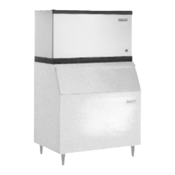
There are 2 models covered in this manual:
•
CME1356, having 5 evaporators
•
CME1656, having 6 evaporators
TABLE OF CONTENTS
Specifications . . . . . . . . . . . . . . . . . PAGE 2
Air Cooled Layout . . . . . . . . . . . . . . . PAGE 3
Water Cooled Layout . . . . . . . . . . . . . PAGE 4
Pre-Installation . . . . . . . . . . . . . . . . . PAGE 5
Stacking . . . . . . . . . . . . . . . . . . . . PAGE 7
Stacking . . . . . . . . . . . . . . . . . . . . PAGE 8
Bin Control: Installation . . . . . . . . . . . . PAGE 9
Bin Control . . . . . . . . . . . . . . . . . . . PAGE 10
Plumbing . . . . . . . . . . . . . . . . . . . . PAGE 11
Electrical . . . . . . . . . . . . . . . . . . . . PAGE 12
After Utility Connections . . . . . . . . . . . . PAGE 13
Component Description and Function . . . . . PAGE 14
System Controller . . . . . . . . . . . . . . . PAGE 15
Initial Start Up . . . . . . . . . . . . . . . . . PAGE 16
Adjustments . . . . . . . . . . . . . . . . . . PAGE 17
Adjustments . . . . . . . . . . . . . . . . . . PAGE 18
How The Electronic Cuber Works . . . . . . . PAGE 20
How The Electronic Cuber Works . . . . . . . PAGE 21
Parts Lists and Wiring Diagrams are Located in the Center of this Manual
Be certain that the information applies to the model
in question. If no model is listed, the information
applies to all models.
This manual is organized in the same way as the
expected use of the machine, it begins with
specifications, goes thru unpacking and setup,
shows where everything is; continues with initial
start up, then describes how it works. After that is
the sanitation section, followed by service diagnosis
and repair.
Sanitation and Cleaning . . . . . . . . . . . . PAGE 24
Additional Maintenance . . . . . . . . . . . . PAGE 25
Additional Maintenance: Water Distributors . . PAGE 26
Service Diagnosis . . . . . . . . . . . . . . . PAGE 30
Service Diagnosis: Components . . . . . . . PAGE 31
PTCR . . . . . . . . . . . . . . . . . . . . . PAGE 32
Operational Characteristics: CME1356 . . . . PAGE 33
Operational Characteristics: CME1656 . . . . PAGE 34
Removal and Replacement . . . . . . . . . . PAGE 36
Access Valves . . . . . . . . . . . . . . . . . PAGE 39
Liquid Charging . . . . . . . . . . . . . . . . PAGE 40
Before Calling for Service . . . . . . . . . . . PAGE 41
May 2000
Page 1
CME1356 and CME1656
Advertisement
Table of Contents

Subscribe to Our Youtube Channel
Related Manuals for Scotsman CME1356


Summary of Contents for Scotsman CME1356
-
Page 1: Table Of Contents
PTCR ..... PAGE 32 Operational Characteristics: CME1356 ..PAGE 33 Operational Characteristics: CME1656 ..PAGE 34 Removal and Replacement . -
Page 2: Specifications
208 volt tap. Change to the 240 volt tap when the voltage supplied to the unit is greater than 229 volts All models will fit a standard, 48" wide Scotsman Ice Storage Bin. Some examples are BH900, BH1100, BH1300, BH1600. There may be other bins that can be used, check Scotsman’s sales... -
Page 3: Air Cooled Layout
Air Cooled Layout 6.00 in MINIMUM FOR 15.2 cm UTILITY CONNECTIONS 6.00 in 15.2 cm MINIMUM FOR AIR VENTILATION BACK VIEW CME1356 and CME1656 26.10 in 66.3 cm MINIMUM BIN TOP OPENING PLAN VIEW 4.20 in 10.15 in 10.7 cm 25.8 cm OPENING .88 DIA. -
Page 4: Water Cooled Layout
CME1356 and CME1656 Water Cooled Layout 6.00 in MINIMUM FOR 15.2 cm UTILITY CONNECTIONS 6.00 in 15.2 cm MINIMUM FOR AIR VENTILATION INLET WATER 3/8" FLARE 23.30 in 59.2 cm BACK VIEW 26.10 in 66.3 cm MINIMUM BIN TOP OPENING PLAN VIEW 4.20 in... -
Page 5: Pre-Installation
NOT covered by warranty. CME1356 and CME1656 Nameplate Serial Number Plate Note: Slope front bins must have an internal baffle. Scotsman’s BH900 has the required baffle. Baffle must be approximately in the position shown in the diagram. Side View May 2000... -
Page 6: Location & Assembly
Level the top edge of the bin front to back and left to right. If the ice machine has not been unpacked, do so now. Remove the carton from the skid. After removal of the shipping straps, lift the ice machine off the skid directly onto the bin. -
Page 7: Stacking
2 existing screws and 1 large and 4 small screws from the kit. Both Machines: 12. Place the top ice machine onto the bottom one. Secure together with hardware from the top machine. Remove left front and left side panels. -
Page 8: Stacking
CME1356 and CME1656 Stacking Mounting Straps and Hardware Front-to-Back Bracket May 2001 Page 8 Upper Unit Gasket on Plastic Wall of Lower Unit Gasket for Metal Edges of Bottom Unit Shield Hanger Bracket Shield... -
Page 9: Bin Control: Installation
Bin Control: Installation The bin control is a thermostat. It must be field installed after the ice machine has been placed on the bin. Before starting, remove the left front panel and any baffle in the bin. 1. Locate bin thermostat bulb. -
Page 10: Bin Control
CME1356 and CME1656 Bin Control Bin Thermostat Bin Thermostat Bracket Capillary Tube Mount Thermostat Insert Bulb Capillary Tube Here Tip Here Attach Thermostat Bulb to Bracket Three-Pronged Knob Minimize Excess Tube in Bin Thermostat and Bracket Attach Bracket to Bottom of Ice Machine... -
Page 11: Plumbing
" The ice storage bin will have a drain out the back or base, depending upon the model. The drain for the ice machine and the ice storage " FPT bin must be SEPARATE or the ice machine’s drain water may run into the bin and MELT THE ICE. -
Page 12: Electrical
CME1356 and CME1656 Electrical All models must be installed with the correct wire size and type per the National Electric Code. Locate the nameplate on the back of the cabinet and find the numbers for Voltage, Phase, Minimum Circuit Ampacity and Maximum Fuse Size. Either fuses or HACR type circuit breakers may be used. -
Page 13: After Utility Connections
___ 9. Is the water pressure adequate? ___ 10. Have the drain connections been checked for leaks? ___ 11. Has the bin interior been wiped clean or sanitized? ___ 12. Have any water filter cartridges been replaced? CME1356 and CME1656 May 2000 Page 13... -
Page 14: Component Description And Function
CME1356 and CME1656 Component Description and Function Reservoir: Contains the water for ice making. Water Inlet Valve: Opens to allow water into the reservoir. Water Level Sensor: Controls the size of the ice cube by measuring how much water is used in a cycle. -
Page 15: Autoiq Controller
LINE THERMISTORS ICE SENSOR ICE SENSOR RESERVOIR WATER LEVEL SENSOR FACTORY USE CME1356 and CME1656 Cycle Definitions: • Freeze: The refrigeration system is operating to remove heat from the evaporators. The compressor, fan motor (if air cooled) and water pump are ON. -
Page 16: Initial Start Up
10. Collect and discard the first batch of ice. Rinse out the bin. 11. Fill out the Customer Evaluation and Warranty Registration. Send it to Scotsman. 12. Replace the left front panel. 13. Inform the user of the location and telephone number of the local service company. -
Page 17: Adjustments
CME1356 and CME1656 Adjustments If there was a problem during Initial Start Up: If an error light came on, check the following. 1. Water error. A water error could have been determined by the AutoIQ Controller if the inlet water valve does not fill the reservoir, or if the water pump does not start and lower the water level. -
Page 18: Adjustments
Water cooled models use a water regulating valve to control how much cooling water flows thru the water cooled condenser. At the top of that valve, located in the back of the ice machine, is an adjustment stem. To Adjust: 1. -
Page 19: How To Operate The Autoiq Controller
3 seconds, the unit will switch off immediately. To Reset Machine (machine off, error light on): First push and release the Off button, then push and release the Freeze button. CME1356 and CME1656 May 2000 Page 19 PUSH BUTTON CONTROL SWITCHES INDICATOR LIGHTS:... -
Page 20: How The Electronic Cuber Works
CME1356 and CME1656 How The Electronic Cuber Works Controller Inputs: 1. Reservoir water temperature. This is measured by a thermistor located in the water pump outlet. 2. Discharge line temperature. This is measured by a thermistor located on the compressor discharge line. -
Page 21: How The Electronic Cuber Works
Hot Gas Valve will start, and more water will be drained out. CME1356 and CME1656 Refrigeration System: The refrigeration system is similar to that of most commercial cube ice machines. Heat is removed from the water and discharged out the condenser during the freeze cycle. -
Page 22: Technicians Only: Freeze Cycle Operational Sequence
CME1356 and CME1656 Technicians Only: Freeze Cycle Operational Sequence Assuming the machine has been operational, the Freeze cycle begins with the end of the Harvest Cycle: • Condenser fan is OFF • Water Inlet Valve is CLOSED • Water Pump may be ON •... -
Page 23: Technicians Only: Harvest Cycle Operational Sequence
Stacked Units: CME1356 and CME1656 If the bottom unit is in harvest and receives a signal from the top unit that it is also in Harvest, the bottom unit will stay in harvest for about 6 minutes. -
Page 24: Sanitation And Cleaning
CME1356 and CME1656 Sanitation and Cleaning It is the User’s responsibility to keep the ice machine and ice storage bin in a sanitary condition. Without human intervention, sanitation will not be maintained. Ice machines also require occasional cleaning of their water systems with a specifically designed chemical. This chemical dissolves mineral build up that forms during the ice making process. -
Page 25: Additional Maintenance
To Sanitize the Ice Storage Bin 1. Remove all ice. 2. Remove baffle. 3. Switch ice machine OFF or wait for it to be in a cleaning cycle. 4. Mix a 1 gallon solution of warm (95-115 and sanitizer. Follow local codes for sanitizer. -
Page 26: Additional Maintenance: Water Distributors
Soak or scrub the distributors in or with a solution of Scotsman Ice Machine Cleaner and warm potable water. 10. Return the water distributors to their normal installed position. -
Page 27: Additional Maintenance: Inlet Water Valve Screen
9. Reverse to reassemble. CME1356 and CME1656 Air Filter Replacement 1. Remove the left front panel. 2. Remove a screw holding one clip to the front panel. -
Page 28: Additional Maintenance: Ice Sensors, Condenser
CME1356 and CME1656 Additional Maintenance: Ice Sensors, Condenser The ice sensors use a system of infrared emitting and receiving components to sense ice. They are located at the bottom of the ice outlet port. They must be free of mineral build up to function properly. -
Page 29: Service Diagnosis: Controller Diagnostic Light Analysis
Reservoir temp. wrong * Machine may be reset by pushing and releasing the Off button, then pushing and releasing the Freeze button. ** See following pages CME1356 and CME1656 Probable Correction Use some ice If all lights are out, check power supply, restore power if off Check thermostat for ice on the bulb. -
Page 30: Service Diagnosis
CME1356 and CME1656 Service Diagnosis Problem or Symptom Possible Cause Unit is off because of Bin controls did not sense a “Harvest Problem” ice falling, unit stayed in harvest until the maximum harvest time ran out. Bin controls or AutoIQ Controller may have failed. -
Page 31: Service Diagnosis: Components
Contactor coil open Open starting components Open windings Internal valve failure Water level too low or not sensed CME1356 and CME1656 Probable Correction Replace fan motor Fan motor unplugged, check for voltage from controller. If none, replace controller. Replace pump Check electrical connections. -
Page 32: Ptcr
CME1356 and CME1656 PTCR The “D” series cubers use a PTCR (Positive Temperature Coefficient Resistor) in place of a conventional start relay and start capacitor. Power from the contactor connects to the PTCR and to the Run Capacitor A wire connects the other terminal of the PTCR to the compressor’s start winding. -
Page 33: Operational Characteristics: Cme1356
Operational Characteristics: CME1356 Cycle Times (minutes): Air Cooled Freeze Harvest Water Cooled Freeze Harvest System Pressures (PSIG): Air Cooled Suction: End of Freeze Suction: Peak in Harvest Discharge: 5 minutes into Freeze Discharge: Minimum in Harvest Water Cooled Suction: End of Freeze... -
Page 34: Operational Characteristics: Cme1656
CME1356 and CME1656 Operational Characteristics: CME1656 Cycle Times (minutes): Air Cooled Freeze Harvest Water Cooled Freeze Harvest System Pressures (PSIG): Air Cooled Suction: End of Freeze Suction: Peak in Harvest Discharge: 5 minutes into Freeze Discharge: Minimum in Harvest Water Cooled... -
Page 35: Removal And Replacement
9. Remove water pump brackets from pump. 10. Reverse to replace. 11. Replace front panel. 12. Re-connect electrical power. CME1356 and CME1656 Inlet Water Valve 1. Remove the left front panel. 2. Shut off the water supply. 3. Push and release the OFF button. -
Page 36: Removal And Replacement
CME1356 and CME1656 Removal and Replacement: AutoIQ Controller Electrical Shock Hazard Disconnect electrical power before beginning service 1. Disconnect the electrical power. 2. Remove the front panel. 3. Remove mounting screw holding controller to cabinet. 4. Touch a metal surface to discharge any static electricity. -
Page 37: Removal And Replacement: System Controller
Note: Replacement float stem depths are factory set, but confirm them before installing the new stem: CME1356 uses a tan float stem CME1656 uses a brown float stem Observe machine for proper cube size after replacement of the float stem. -
Page 38: Removal And Replacement: Fan Blade And/Or Fan Motor
CME1356 and CME1656 Removal and Replacement: Fan Blade and/or Fan Motor 1. Disconnect electrical power. Electrical Shock Hazard Disconnect electrical power before beginning service 2. Remove left front and top panels. If stacked, removal is possible thru the front only. -
Page 39: Access Valves
However, critical items will be noted here. Refrigerant: 1. This ice machine uses R-404A or HP62 as a refrigerant. It has several unique characteristics. A. It is a near-azeotrope, and must be liquid charged. -
Page 40: Liquid Charging
CME1356 and CME1656 Liquid Charging Because R-404A is a near-azeotrope, only liquid refrigerant can be used to recharge the refrigeration system. To do that may take some special techniques: 1. Use an electronic scale to measure the charge. 2. Place a drum or cylinder of R-404A on the scale, liquid out side up (check container). -
Page 41: Before Calling For Service
Before Calling for Service Check the following: 1. Has the water supply to the ice machine or building been shut off? If yes, the ice machine will automatically restart within 25 minutes after water begins to flow to it. 2. Has power been shut off to the ice machine? If yes, the ice machine will automatically restart when power is restored.
Need help?
Do you have a question about the CME1356 and is the answer not in the manual?
Questions and answers