
Related Manuals for Hurst Jaws Of Life eDRAULIC SC 250 E2

Summary of Contents for Hurst Jaws Of Life eDRAULIC SC 250 E2
- Page 1 Instruction manual for rescue equipment eDRAULIC combi tools SC 250 E2 SC 358 E2 SC 757 E2 273023085 EN Edition 02.2017 replaces 10.2016 (Original instruction manual)
-
Page 2: Table Of Contents
Content Page 1. Danger classifications 2. Product safety 3. Intended use 4. Functional description 4.1 Description 4.2 Structure of rescue devices 4.3 Hydraulic circuit diagram 4.4 Operating movement controls 5. Operation 5.1 Battery or power supply for eDRAULIC device 5.2 Operating the star grip 6. Cutting, spreading, pulling, squeezing 6.1 Safety notes 6.2 Cutting... - Page 3 Content Page 10. Troubleshooting 11. Technical data 11.1 eDRAULIC combination device 11.2 Noise emission (based on standard EN ISO 3744) 11.3 Operating and storage temperature ranges 11.4 Oscillation / vibration 11.5 Torques for central bolts 11.6 Cutting performance 12. Accessories 12.1 Batteries 12.2 Battery charger 12.3 Power supply 12.4 Chain sets 13. Instructions regarding disposal...
-
Page 4: Danger Classifications
1. Danger classifications We differentiate between various different categories of safety instructions. The table shown below provides an overview of the assignment of symbols (pictograms) and signal words to the specific danger and the possible consequences. Damage / Pictogram Keyword Definition Consequences injury to Death or severe DANGER! Immediate danger injury Potentially Potential death or WARNING! dangerous serious injury situation Less dangerous Minor or slight CAUTION! situation injury Damage to the equipment, Risk of damage damage to the ATTENTION! to property/ environment, environment damage to surroundings Handling tips and No injury/damage other important/ to persons/... -
Page 5: Product Safety
2. Product safety HURST products are developed and manufactured to ensure the best performance and quality when used as intended. The safety of the operator is the most important consideration in product design. Furthermore, the operating instructions are intended to help you use HURST products safely. The generally applicable legal and other binding regulations pertaining to the prevention of accidents and protection of the environment apply and are to be complied with in addition to the operating instructions. The equipment may only be operated by persons with appropriate training in the safety aspects of such equipment, otherwise, there is a risk of injury. We would like to point out to all users that they should carefully read the operating instructions and the instructions they contain before they use the equipment and carefully follow them. We further recommend that you have a qualified trainer show you how to use the product. WARNING / CAUTION! The operating instructions for accessories must also be taken into account! Even if you have already received instructions on how to use the equipment, you should still read through the following safety instructions again. - Page 6 Immediately report any All bolted connections must changes that occur (including be checked for leaks and changes in operating externally visible damage, behavior) to the appropriate which must be repaired persons/departments! If immediately! Escaping necessary, the equipment is hydraulic fluid can cause to be shut down immediately injuries and fires. and secured! In the event of malfunction, Do not carry out any changes immediately deactivate the (additions or conversions) device and secure it. Repair to the equipment without the fault immediately. obtaining the prior approval of HURST. Observe all safety and danger All safety and danger information on the device and instructions on the device in the operating instructions. must always be complete and in a legible condition. Any mode of operation which Repairs to the equipment compromises the safety and/ may only be carried out by or stability of the device is a trained service technician forbidden! with specific knowledge of the device. Safety devices may never be Only genuine HURST disabled!
- Page 7 Please ensure that you do not Please ensure that the become entangled in cables battery contacts are not short- and trip when working with or circuited. transporting the device. The build-up of static charges Only touch broken-off or and therefore possible cut-off parts while wearing sparking must be avoided protective gloves, as the torn / when handling the device. cut edges can be very sharp. Protect the eDRAULIC The eDRAULIC devices are devices against humidity and not suitable for underwater moisture use. The equipment is filled with When working with or storing hydraulic fluid. This hydraulic the equipment, ensure that fluid can be detrimental to the function and the safety health if it is swallowed or of the equipment are not its vapor is inhaled. Direct impaired by the effects of contact with the skin must severe external temperatures be avoided for the same and that the equipment is not reason. Also, when handling damaged in any way. Please hydraulic fluid, note that it can note that the equipment can negatively affect biological also heat up over a long systems.
-
Page 8: Intended Use
The generally applicable, legal and other binding national and international regulations pertaining to the prevention of accidents and protection of the environment apply and are to be implemented in addition to the operating instructions. WARNING / CAUTION / ATTENTION! The device is intended exclusively for the purpose stated in the operating instructions (see chapter "Proper Use"). Any other use is not in accordance with its designated purpose. The manufacturer/supplier is not liable for any damage resulting from improper use. The user bears sole responsibility for such use. Proper use includes observance of the operating instructions and compliance with the inspection and maintenance conditions. - Page 9 WARNING / CAUTION / PLEASE NOTE! The following may not be cut / squeezed: - live cables - prestressed and hardened parts such as springs, spring steels, steering columns and rollers - pipes under gas or liquid pressure, - compound materials (steel/concrete) - explosive bodies such as airbag cartridges The operating pressure placed on the rescue device may only be directly changed after consultation with HURST. A change in settings may result in damage to property and/or injuries.
-
Page 10: Functional Description
4. Functional description 4.1 Description The combination devices have been designed in such a way that a hydraulically operated piston activates mechanical joints symmetrically to open or close a set of two opposite blade arms, thus enabling objects to be cut. For all devices, the movement is activated by means of a valve in the form of a star grip. All devices guarantee the dead man's switch and the full load-supporting function when the star grip is released. HURST eDRAULIC devices do not need to be connected to an external hydraulic source (e.g. a motor pump). Generation of the required hydraulic pressure takes place within the body of the device. Either a battery or an external power supply must be connected as an energy source. You can choose which energy source you wish to use. Both the accumulator battery and the mains power unit can be inserted into the opening provided in the body of the tool. They are then automatically locked into position. You can extend the operating time of your eDRAULIC device by using several batteries. The batteries can be recharged after use, using a suitable external charger. If you are making use of an external power supply, the device can be used for an almost unlimited time. This time is only limited by the external energy source and the overheating switch of the power supply. To allow you to select the best possible energy supply for your eDRAULIC device, neither the battery nor the power supply form part of the delivery scope. You will find suitable bat- teries and power supplies in the HURST accessories list. eDRAULIC devices come with standard light fittings to facilitate work under poor light conditions. The light-emitting diodes attached on the operating side light up the work area. The main switch has also been equipped with a ring light, so that you can immediately detect whether the device is switched on or not. When exchanging the battery or power supply, the connection slot will light up for approximately 30 seconds. -
Page 11: Structure Of Rescue Devices
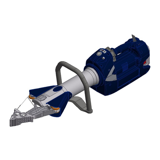
4.2 Structure of rescue devices 4.2.1 Combination tool SC 250 E2 1 Star grip 2 Main switch 3 Quick exchange battery or power supply 4 Release button for bat- tery and power supply 5 Handle 6 Ventilation slots 7 Blade arms 8 Pivot bolt with secured 9 Plastic housing 10 Tool body 11 Protective cover 12 Light SC 358 E2 SC 757 E2 13 Exchangeable tip at- tachments... -
Page 12: Hydraulic Circuit Diagram
4.3 Hydraulic circuit diagram Below a simplified hydraulic ram representing the tool is depicted. A = tool B = star grip valve cutting / gripping / pulling / squeezing spreading / opening 4.4 Operating movement controls The piston movement is controlled by the star grip on the attached valve (see illustration below). Star grip 5. Operation 5.1 Battery or power supply for eDRAULIC device Commissioning Before initial operation, the battery (where used) of the rescue device must be fully loaded, using the external charger. -
Page 13: Operating The Star Grip
Procedure: 1. Unplug the power supply (where used) from the mains. 2. Fully press down the two unlocking buttons and carefully pull the battery or power supply out of the device. Do not use force! Connection slot 3. The battery can now be recharged in the charger (please take note of the separate operating instructions for the charger and the batteries to be used); alternatively, the power supply can be replaced. 4. Insert the recharged or new battery into the eDRAULIC device until it reaches the stop. The battery or power supply will be automatically locked when correctly oper- ated. 5.2 Operating the star grip (also see chapter on "Operating movement control") Open the device ( Turn the star grip in the direction of the corresponding symbol (open) and hold it in this position. Close the device ( Turn the star grip in the direction of the corresponding symbol (close) and hold it in this position. "Dead-man’s" function: Following release, the star grip automatically returns to the central position, fully guaranteeing load retention. -
Page 14: Cutting, Spreading, Pulling, Squeezing
Note on the operation of the eDRAULIC with a rechargeable battery: If the rechargeable battery remains in the eDRAULIC device with the main switch on, but without activating the star grip, the rechargeable battery will switch itself off after some time (approximately 10 - 60 minutes, depending on the type of battery). If the star grip is then activated, the eDRAULIC device will not switch itself on. In order to resume work with the device, the eDRAULIC device must first be switched off at the mains and then switched on again. Alternatively, the capacity display on the rechargeable battery can be activated or the battery may be briefly unplugged and replugged again. 6. Cutting, spreading, pulling, squeezing 6.1 Safety notes Before rescue work can commence, the object must be stabilized in its current position. Ensure that the objects to be worked on are adequately underpinned and/or supported to ensure that there is no risk of sliding or shifting. -
Page 15: Cutting
It is strictly prohibited to reach into the path of the rescue device (e.g. between the blades and the material/ object to which the force is to be applied)! CAUTION / PLEASE NOTE! The strong effect of the force of the rescue equipment during operation could cause pieces of the vehicle to break off or fly off, posing a danger to persons. - Page 16 During cutting, the gap between the blade tips (in the transverse direction) must not be exceeded, otherwise the blade is in danger of breaking: eDRAULIC cutting device max. gap at the blade tips [mm] / [in.] SC 250 E2 / 0.12 SC 358 E2 / 0.12 SC 757 E2 / 0.12 ATTENTION! Where possible, avoid cutting through high-strength parts of the vehicle body...
-
Page 17: Spreading
Step 2: The bolt can then be gripped by the flange and pulled out up to the limit stop. The limit stop will prevent the bolt from being pulled out entirely. This means that it cannot be lost. Step 3: Pull the spreader tip forwards to remove it. Attaching the spreader tip: Attachment of the spreader tip takes place in the reverse sequence. Ensure that the bolt is always completely pushed in and engages. If the bolt has not engaged, this may result in the tip inadvertently coming loose while in use. This in turn could result in damage to the rescue equipment. The rescue device could also slip or parts could be flung off, resulting in injuries to both the operator and the crash victim. Care must also be taken that the bolt does not inadvertently come loose while the device is in use. 6.3 Spreading Use the front of the tips only to increase an existing gap. To increase grip and to avoid having the tips slip or break out of the part to be processed, the grip should be reapplied at an early stage. The highest force develops in the rear area of the plug-on tip or in the rear spreading area of the combination blades. WARNING / CAUTION / PLEASE NOTE! The light metal alloy arms may not be damaged. Spreading Enlarging a gap approx 25 mm... -
Page 18: Pulling
Working surface is too small, Tips get a safe grip. Work with the tips only. tips slip off. Do not damage the Only for increasing the size spreader arms! of a gap (not suitable for spreading) 6.4 Pulling WARNING / CAUTION / PLEASE NOTE! The light metal alloy arms may not be damaged. - HURST chain sets must be used for pulling. - When using a chain for pulling, make sure that the pins and hooks are positioned correctly so that the chain cannot slip. - Only chain sets in perfect condition may be used. - The pulling chains must be checked by an expert at least once a year. - Also consult the separate operating instructions for the corresponding chain set! Attachment hole for chain sets... - Page 19 The connecting pieces for HURST chain sets are fastened to the blades using load bolts in holes "A". (see illustration on the right) Chain sets: for SC 250 E2: KSV 8/50 for SC 358 E2: KSV 11 for SC 757 E2: KSV 13 NOTE: Also take note of all the instructions and regulations in the separately provided operating instructions for the chain sets. Pulling with SC 757 E2 To use the SC 757 E2 for pulling, the spreader tip must first be removed (see 6.2). The pulling attachment “A” is then mounted. First pull out the bolt of the pulling attachment up to the limit stop, slip the pulling attachment onto the arm and push in the bolt completely until it engages (also see Section 6.2, “Removing and attaching the Spreader Tip”) in this regard. The matching chain lock “C” can then be fixed to hole “B” of the pulling attachment (see separate operating instructions for chain lock).
- Page 20 WARNING / CAUTION / PLEASE NOTE! The pulling attachments must be mounted in such a way that the two surfaces, „A“ and „B“ are always in the same plane. This ensures that the pulling force is symmetrically applied. If this instruction is disregarded, this may result in excessive load being placed on the cutting arms, resulting in injuries to the operator or crash victim. RIGHT WRONG WRONG...
- Page 21 Pulling with SC 358 E2 To use the SC 358 E2 for pulling, the spreader tip must first be removed (see 6.2). The pulling attachment “A” is then mounted. First pull out the bolt of the pulling attachment up to the limit stop, slip the pulling attachment onto the arm and push in the bolt completely until it engages (also see Section 6.2, “Removing and attaching the Spreader Tip”) in this regard. The matching chain lock “C” can then be fixed to hole “B” of the pulling attachment (see separate operating instructions for chain lock).
-
Page 22: Squeezing
6.5 Squeezing WARNING / CAUTION / PLEASE NOTE! The light metal alloy device arms may not be damaged. Squeezing may only take place near the tips (see figure below). Squeezing area... -
Page 23: Dismantling The Equipment / Deactivation Following Operation
7. Dismantling the equipment / deactivation following operation Once work has been completed, the device arms should be closed until the tips are only a few millimeters apart. This relieves the hydraulic and mechanical strain on the equipment. NOTE: Never store the eDRAULIC devices with fully closed arms! By fully closing the arms, hydraulic and mechanical tension may develop in the device. Clean the rescue device after each operation and grease both the metallic and the mechanically movable parts. The lock of the plug-on tips should also be greased from time to time. Greasing provides protection against excessive wear and tear or corrosion. Avoid storing the rescue equipment in a damp environment. 8. Maintenance and service The devices are subject to very high mechanical stresses. A visual inspection must therefore be carried out after every use and at least one visual inspection must be carried out every six months. These inspections enable the early detection of wear and tear, which means that punctual replacement of these wearing parts prevents breakage. Regularly check the torque of the pivot bolt on the combination tools. (You will find the torques for the pivot bolt in the chapter on "Technical Data".) An annual inspection of the tool is due once a year. This inspection must be performed by a person with the necessary expertise. This means that the person must possess adequate... -
Page 24: Edraulic Combination Tools
8.1 eDRAULIC combination tools Inspections to be carried out: Visual Inspection Combination tool • Opening width of the blade arms on the tips (see chapter "Technical data"), • General tightness (leaks), • Operability of the star grip - check the automatic return into middle position after release (dead man’s function), • Existence and stability of handle, • Labels complete and legible, • Covers in perfect condition, • Check the torque of the pivot bolt (for torque M see "Technical Data"). • Blade arms free of cracks and nicks or deformations on the cutting surfaces, • Cutting surfaces fit on top of each other without making contact, • The sliding plates, bolts and retaining rings of the blade arms are in place and in good condition, • Illumination of main switch, work area and connection shaft fully functional. Battery and power supply • Casing undamaged • Electrical contact surfaces clean and undamaged • Cable undamaged... -
Page 25: Protective Equipment
8.2 Protective equipment Inspections to be carried out: • Check the protective equipment used on / in the vicinity of the rescue device. Pay particular attention to the protective cover for the movable parts (there may be no cracks!). 8.3 Checking the filter in the battery shaft The air suction filter is to be checked at least once a year or after use in a dusty environment. The filter can be checked from the outside if the mains unit (or battery) is removed (see illustrations below). If the filter is severely contaminated, it will need to be replaced. Procedure: Tilt the respective device as shown in the illustration. -
Page 26: Repairs
9. Repairs 9.1 General information Service work may only be performed by the device manufacturer or by personnel trained by the device manufacturer and authorized HURST dealers. Only HURST spare parts may be used to replace all components (see spare parts list), as special tools and compliance with, assembly instructions, safety aspects and inspections are required (see also chapter "Maintenance and Servicing"). During assembly, ensure that all components are particularly clean, as dirt can damage the rescue equipment! WARNING / CAUTION / PLEASE NOTE! Protective clothes must be worn when repairs are being carried out, as the devices may also be pressurized when not in operation. -
Page 27: Preventive Service
9.2 Preventive service 9.2.1 Care instructions The outside of the device should be cleaned with a damp cloth from time to time (not the electrical contacts in the connection slot, on the battery and on the power supply). In addition, the metal surfaces are to coated with a suitable medium to counteract corrosion (not the electrical contacts in the connection slot, on the battery and on the power supply). (In case of doubt, contact your authorized HURST dealer or HURST directly!) 9.2.2 Function and load test If there is any doubt regarding the safety or reliability of a device, a function and stress test... - Page 28 Work steps: 1. First of all, carefully clean the rescue equipment. 2. Remove the two fixing screws "A" and remove the protective cover "B". To do this, first pull the rounded rear edge outwards and then backwards through the hand grip, as the edges of the protective cover adjoining the cylinder body are kept in place by guide grooves. If necessary, loosen the hand grip and move it backwards to obtain sufficient space to pull it out. CAUTION / PLEASE NOTE! When operating the device with the hand guard removed, there is an increased risk of injury caused by the exposed, moving elements. 3. Move the blade arms on the until bolt “E” is easily accessible. Now switch off the device and remove the battery or unplug the power supply from the device.
- Page 29 4. First remove the grub screw "G", then the central bolt nut "H" and then pull out the central pin "J". 5. Remove the locking rings “M” and push the pin “N” out. You can then pull out the blades “O” and the slide plates “P”. 6. Release the fixing screws “K” and remove them. The handle “L” can now be pulled out forwards. 7. The work steps must be carried out in reverse order to fit the new parts. ATTENTION! Apply HURST special grease to all sliding surfaces! NOTE: The torque required can be taken from the spare parts list of your particular unit.
- Page 30 9.3.2 Replacing the blades, protective cover and hand grip of the SC 250 E2 combination tool NOTE: The illustrations show the equipment with the blade arms of the cutter tool. Assembly and disassembly are identical for the combination tool! Components to be Required work steps replaced Protective cover 1. - 9. and 10. Pivot bolt 1., 5. and 10.
- Page 31 4. First remove screw “D”. Then push the hand guard “E” in the depicted direction until the bolts “F” are easily accessible. 5. Remove self-locking nut “H” and push the pivot bolt “G” out. 6. Remove the retaining rings “K” and push out bolt J. 7. Now, you can remove blade “L” and sliding plates “M”.
- Page 32 8. Fold in the lever elements “N”. 9. L ast of all, pull the protective sleeve "E" off the device, as shown above. 10. The work steps must be carried out in reverse order to fit the new parts. ATTENTION! Apply HURST special grease to all sliding surfaces! NOTE: The torque required can be taken from the spare parts list of your particular unit. ATTENTION! The nut of the pivot bolt and the pivot bolt itself are matched by a special procedure. Therefore they must only be changed as a set by using a new set! Because of the special procedure used, unscrewing of the nut while working will be minimized and a resulting blade crack will be prevented. The nuts can be unscrewed and tightened up to 10 times without affecting the service performance!
- Page 33 9.3.3 Decals All damaged and/or illegible decals (safety notices, type plate etc.) must be replaced. Procedure: 1. Remove damaged and/or illegible decals. 2. Clean surfaces with industrial alcohol. 3. Affix new decals. Take care to affix the labels in the correct positions. If this is no longer known, you should ask your authorized HURST dealer or contact HURST directly.
-
Page 34: Troubleshooting
10. Troubleshooting Fault Check Cause Solution The motor does not The main switch The star grip was In order to resume start after activating is not illuminated, not used for some work with the device, the star grip. although it has not time (at least 10 the eDRAULIC been switched off. minutes) during device must first battery operation. be switched off at The rechargeable the mains and then battery has switched on again. switched itself off. Alternatively, the capacity display on the rechargeable battery can be activated or the battery may be briefly unplugged and replugged again. Blade arms move Battery fully Battery flat Charge battery slowly or jerkily charged? - Page 35 Fault Check Cause Solution Blade arms do Battery fully Battery flat Charge battery not move when charged? Battery defective Replace battery operated. Power supply cable Power supply cable Replace power connected? defective supply cable Device defective Repair by an authorized dealer, by personnel specially trained by HURST, or by HURST itself Device does not Device defective Repair by an perform at its given authorized dealer, by power personnel specially trained by HURST, or by HURST itself Following release, Casing damaged or Damage to the Repair by an the star grip star grip operation torsion spring for authorized dealer, doesn’t return to...
-
Page 36: Technical Data
Contact an authorised HURST dealer or the HURST Customer Service Department directly if the malfunctions cannot be rectified. The address for the HURST Customer Service department is: HURST JAWS OF LIFE, INC A Unit of IDEX Corporation 711 N. Post Road Shelby, NC 28150 USA Phone: (704) 487-6961 Fax: (704) 487-7271 e-mail: contacthurst@idex.com 11. Technical data Since all values are subject to tolerances, minor differences may occur between the data on your equipment and the data in the following tables. The values may also differ because of reading inaccuracies and/or tolerances in the measuring equipment used. -
Page 37: Edraulic Combination Device
11.1 eDRAULIC combination device Device type SC 250 E2 SC 358 E2 Item number 273025000 273023000 [mm] 849 x 215 x 262 956 x 237 x 281 Dimensions (excluding Battery) L x W x H [in.] 33.4 x 8.46 x 10.3 37.7 x 9.3 x 11.1 [mm] Min. cutting opening [in.] 12.2 [kN] Max. - Page 38 Device type SC 757 E2 Item number 362R542 [mm] 1033 x 294 x 285 Dimensions (excluding battery) L x W x H [in.] 40.7 x 11.5 x 11.2 [mm] Min. cutting opening [in.] 14.5 [kN] Max. cutting force (rearmost cutting point) [lbf.] 198000 Minimum spreading force [kN] (at a distance of 25 mm / [lbf.] 9218 0.98 inches from the tips) [kN] LSF spreading force...
-
Page 39: Noise Emission (Based On Standard En Iso 3744)
11.2 Noise emission (based on standard EN ISO 3744) SC 250 E2, Device type SC 358 E2, SC 757 E2 Battery type used for device Lithium/ion Idling [dB(A)] (measured at a distance of 1 m, according to EN) Full load [dB(A)] (measured at a distance of 1 m, according to EN) Idling [dB(A)] (measured at a distance of 4 m, according to NFPA) Full load [dB(A)] (measured at a distance of 4 m, according to NFPA) 11.3 Operating and storage temperature ranges Operating temperature [°C] / [°F]... -
Page 40: Cutting Performance
11.6 Cutting performance Device type Max. cutting material dimensions Round Flat Round Square Rectangular material material tube tube tube [mm] [mm] [mm] [mm] [mm] [in.] [in.] [in.] [in.] [in.] 80x10 60,3x2,9 50x4 80x40x3,0 SC 250 E2 1.02 3.15x0.39 2.37x0.11 1.97x0.16 3.15x1.57x0.12 130x10 88,9x4,0... -
Page 41: Accessories
12. Accessories 12.1 Batteries Only HURST lithium-ion rechargeable batteries may be used to operate eDRAULIC devices. These guarantee optimum performance and maximize the operating time of the eDRAULIC devices. NOTE: To ensure maximum Charging state operating time and display maximum uptime, you must make sure that the battery is always Query button fully charged before connecting it to a rescue device. Technical Data nom. Voltage Capacity Energy Weight Unit V DC Battery type 1 25.2 0.92 2.03 Battery type 2 25.2 0.94 2.07 Battery Type 1: Display code Capacity = 75...100% - LED 1-4 lights up Capacity = 50...75% - LED 1-3 lights up... -
Page 42: Battery Charger
12.2 Battery charger Only the "eDRAULIC Power Pack Charger" may be used for the lithium-ion batteries. NOTE: Pay strict attention to the separate operating instructions for the battery charger. 12.3 Power supply The eDRAULIC devices have a specially developed power supply with which the devices can be directly connected to the power grid. The power supply converts the alternating current from the power grid into direct current, which means that it can be used instead of the battery. Mains plug Cable Adapter Cable Filter Structure: There is an adapter on one side of the power supply which can be simply inserted into the connection slot of the devices and locked. The other side has a mains plug. Both are connected by a cable. The mains plug is a Schuko plug with Protection Classification IP 68 or a US plug. The integrated filter is appropriate for the conversion of AC voltage to DC... -
Page 43: Chain Sets
12.4 Chain sets Chain sets are required in order to be able to perform pulling operations with the eDRAULIC combination tool (see chapter, "Pulling"). Suitable chain sets: for SC 250 E2: KSV 8/50 for SC 358 E2: KSV 11 for SC 757 E2: KSV 13 13. Instructions regarding disposal Please duly dispose of all packaging materials and removed items. Electrical equipment, accessories and packaging should always be disposed of in an environmentally compatible way. Only for EU countries: Do not dispose of electrical equipment with your household waste! According to the European Directive 2002/96/EC governing electrical and electronic waste and their application in national legislation, old electrical equipment must be separately collected and recycled in an environmentally compatible manner. - Page 44 Please duly dispose of all packaging materials and removed items. HURST JAWS OF LIFE, INC A Unit of IDEX Corporation 711 N. Post Road Shelby, NC 28150 USA Phone: (704) 487-6961 Fax: (704) 487-7271 e-mail: contacthurst@idexcorp.com Made in USA eDRAULIC2_manual_273023085_en.indd © Copyright 2017 Hurst Jaws of Life, INC...
Need help?
Do you have a question about the eDRAULIC SC 250 E2 and is the answer not in the manual?
Questions and answers