Table of Contents
Advertisement
Quick Links
Advertisement
Table of Contents

Summary of Contents for Precision Rated Optics OFS-941V
- Page 1 OFS-941V Fusion Splicer Operation Guide V.11.17.17...
-
Page 2: Table Of Contents
OFS-941V Table of Contents Technical Specifications ...........................4 Battery precautions ..............................5 Installation.................................6 Safety warnings and precautions ..........................6 Operational safety warnings ..........................6 Maintenance and external care precautions ......................7 Transport and storage precautions ........................7 Installation ................................7 Splicer overview ..............................8 Power supply ................................9 Basic Operation ..............................10 Turning on the splicer ............................10... - Page 3 OFS-941V Dust check ................................25 Motor calibration ..............................25 Arc calibration ..............................26 Electrode setting ..............................26 Update software ..............................26 Other Functions & Utilities ...........................27 Data storage ................................27 System setting ...............................27 System information ..............................29 Appendix I ................................30 Appendix II ................................31 List of error messages ............................31 Appendix III ................................33...
-
Page 4: Technical Specifications
OFS-941V Technical Specifications Applicable fiber type SM(ITU-T G.652&G.657) / MM(ITU-T G.651) / DS(ITU-T G.653)/ NZDS(ITU-T G.655) Fiber count Single Applicable fiber cables 0.25mm - 3.0mm / Indoor cable Cladding diameter: 80~150μm, Applicable fiber diameter Coating diameter: 125~1000μm Splice loss SM: 0.03dB, MM: 0.02dB, DS: 0.05dB, NZDS: 0.05dB, G.657: 0.03dB... -
Page 5: Battery Precautions
OFS-941V Battery precautions DO NOT collide the battery with sharp or hard objects. DO NOT transport or store the battery with metals simultaneously. DO NOT throw, drop, impact or bend the battery. DO NOT strike the battery with hammers or tread on it. -
Page 6: Installation
• Please use OFS-941V designed charger only. Do not place any heavy objects on the AC power cord. Keep the power cord away from heat source. Using an improper cord or a damaged cord may cause fuming, electric shock or equipment damage and may even result in fire, injury or death. -
Page 7: Maintenance And External Care Precautions
OFS-941V Maintenance and external care precautions • Always avoid using hard objects to clean V-grooves and electrodes. • Always avoid using acetone, thinner, benzol or alcohol when cleaning any parts of the splicer, except for the places advised. • Use a dry cloth to remove dust and dirt from the splicer. -
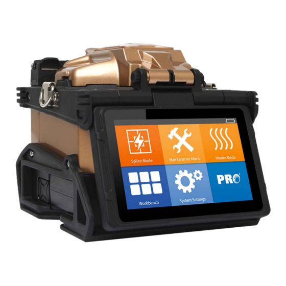
Page 8: Splicer Overview
OFS-941V Splicer overview On/Off Heater Loop Control Buttons On/Off Power supply/ Battery 888-545-1254 | www.PrecisionRatedOptics.com... -
Page 9: Power Supply
OFS-941V Power supply Battery Switch off the splicer. Press the [Release] button at the side of the splicer and take out the battery from the splicer. Charge the battery Connect the battery charger to the battery. Charging progress is indicated by five lit LEDs continuously sweeping from 20% to 100% on the battery indicator (see below). -
Page 10: Basic Operation
OFS-941V Basic Operation Turning on the splicer Press [Power] key on the operation panel, and wait the splicer to be turned on and move to Workbench page. Adjusting the monitor position Users can adjust the monitor position by moving it with a desired angle in purpose of operation convenience. - Page 11 OFS-941V Touch screen On/Off Users can choose their operation styles based on their operating patterns. When the touch screen switch is [Off], users can only perform operation by pressing buttons. When the touch screen switch is [On], users can perform operation by both pressing buttons or touching the screen.
-
Page 12: Preparing The Fibers
OFS-941V Preparing the fibers 3 Steps should be carried out before splicing: Step 1: Strip the fiber Remove at least 50mm of secondary coating (valid for both tight and loose tube secondary coating) and approximately 30~40mm of primary coating with an appropriate stripper. -
Page 13: How To Make A Splice
OFS-941V How to make a splice Placing the fibers • Open the windproof cover. • Raise the fiber holders. • Place the fiber into V-grooves and make sure that the fiber ends are placed between the edge of V- grooves and the electrode ends. -
Page 14: How To Protect The Splice
OFS-941V Splicing • Select any appropriate splice mode. • Start splicing by pressing [SET] button. Note: If the splicer is set as “Auto mode”, splicing will start automatically once the windproof cover is closed. How to protect the splice After splicing, put the fiber with heat-shrink sleeve into the heat oven. Press [HEAT] button to execute heat- shrink process to strengthen the splice point. -
Page 15: Splice Programs
OFS-941V Splice Programs OFS-941V has an intuitive and simple but very powerful program structure to operate. Splice programs define arc currents, splice times as well as various parameters used when performing a splice. Therefore, it is essential to select the correct splice program. There are a number of “preset” splice programs for common fiber combinations. -
Page 16: Selecting A Splice Program
OFS-941V Selecting a splice program Select [Splice mode] from the main menu. Select [Splice mode] and select [Select splice mode]. Select an appropriate splice mode Selected splice mode appears on the screen. Press [RESET] button to return to initial interface page. -
Page 17: General Splicing Steps
OFS-941V General splicing steps This section explains the steps involved in automatic splicing process and describes how various program parameters are related to this process. The normal splicing process can be divided into two sections; pre-fusion and fusion. Pre-fusion During pre-fusion, the splicer performs automatic alignment and focusing, where the fibers are subjected to a low pre-fuse current for cleaning purposes;... -
Page 18: Splice Program Parameters Under General Splicing Process
OFS-941V Splice program parameters under general splicing process Parameter Description A list of splice modes stored in the splicer database. Upon inputting the appropriate mode, the selected splice mode Template stored in database area is copied to a user-programmable area. -
Page 19: Splice Option
OFS-941V Splice Option Setting up splice mode Select [Splice option] in menu. Select a parameter to be changed Parameter Description If “Auto Start” is set to “On”, splicing starts automatically as soon as the windproof cover is closed. Auto Start Fibers should be prepared and placed into the splicer in advance. -
Page 20: Heater Mode
Select a heating mode that best matches with the protection sleeve used. For each type of protection sleeve, OFS-941V has its optimum heating mode. These modes can be found in the database area for reference. Copy the appropriate mode and paste it to the user–programmable area. Users can edit those parameters. -
Page 21: Editing Heat Mode
OFS-941V Editing heat mode Heating conditions stored in heater mode can be edited or changed. Select [Edit Heat Mode] in Select the mode to be edited. [Heater mode] menu. Select the parameters to be edited. www.PrecisionRatedOptics.com | 888-545-1254... -
Page 22: Deleting Heat Mode
OFS-941V Deleting heat mode Select [Heater Mode] menu. Select [Delete Heat Mode]. Select the heat mode to be deleted. Note: The gray modes (40mm, 60mm) are the system preset initial heat modes which cannot be deleted. Heat mode parameters Parameter Description Set sleeve type. -
Page 23: Maintenance Menu
Do not pull out wiring when replacing electrode. Do not exceed the normal finger strength when tightening screw. • Precision Rated Optics strongly recommends all users to do stabilizing electrodes and arc calibration after electrodes replacing to keep good splice results and splice strength (Details are described below). -
Page 24: Stabilize Electrodes
Perform stabilizing electrodes 20 times consecutively to precisely locate the electrodes position. Diagnostic test OFS-941V has a built-in diagnostic test function that allows the user to evaluate several critical variable parameters with only one simple step. Perform this function in case of splicer operation fault. -
Page 25: Dust Check
OFS-941V Execute [Diagnostic test], then the following checks will be made. Parameter Description LED Calibration Measure and adjust the brightness of LED. Check the optical path for dust or dirt and judges whether they disturb fiber observation. If Dust Check contamination exists, press the return button twice to display the location. -
Page 26: Arc Calibration
Atmospheric conditions such as temperature, humidity and pressure are constantly changing, which creates variability in the arc temperature. OFS-941V is equipped with temperature and pressure sensors that are used in a constant feedback monitoring control system to maintain the arc power at a stable level. However, changes in arc power due to electrode wear and glass adhesion cannot be calibrated automatically. -
Page 27: Other Functions & Utilities
OFS-941V Other Functions & Utilities Data storage This splicer stores up to 2000 splicing results. Contents of data stored are different depending on the splicing mode. Display splice record Splicing results stored in the splicer can be displayed. • Select [Display Splice Record] in [Data Storage] menu. - Page 28 OFS-941V Monitor Position The direction of the splicer display before shipping from the factory is set to “Front”, but users can change it to “Rear”. When [Monitor position] is changed, the direction of the arrow keys is reversed. Changing monitor position 1) Select [Monitor Position] in [System Setting] menu.
-
Page 29: System Information
OFS-941V System information Select [System Information]. The following information is displayed. Parameter Description Machine Serial Number Display the serial number of the splicer Software Version Display the version of the software FPGA Display the version of FPGA Total Arc Count... - Page 30 OFS-941V Appendix I High splice loss solutions Symptoms Cause Corrective measures Core axis deviation Dust on the Ribbon Groove or holder Clean the Ribbon Groove or holder Core angle Dust on the Ribbon Groove or holder Clean the Ribbon Groove or holder Bad condition of fiber’s tip...
-
Page 31: List Of Error Messages
OFS-941V Appendix II List of error messages During the splice operating process, if the error messages are shown on the screen, please follow the solution precisely as shown in the list below. If it is not possible to solve the problem, the splicer may require service by a qualified service center. - Page 32 OFS-941V Check the condition of the fiber cleaver. If the blade is worn, rotate the blade to a new position Bad fiber end face or change a new one, and then re-prepare the fibers. Cleave Angle Over Limit Increase the [Cleave Angle Limit] to an [Cleave Angle Limit] is set too low.
-
Page 33: Frequent Questions And Troubleshooting
OFS-941V Appendix III Frequent questions and troubleshooting Note: The solutions of common faults for reference are as follows. Please contact sales agents for further support if needed. Power does not turn off when pressing ON/OFF button. • Press and hold the key until the LED blinks, and then release the button to turn off the splicer. - Page 34 OFS-941V Mismatch between estimated splice loss and actual splice loss. • The estimated loss is just an estimated number by calculation, for reference only. • The optical components of the splicer need to be cleaned. Fiber protection sleeve does not shrink completely.
- Page 36 Precision Rated Optics, Inc Corporate Office Billing & Processing PO Box 877 Trexlertown, PA 18087 Precision Rated Optics, Inc Product Distribution Center Manufacturing & Testing 9999 Hamilton Blvd Breinigsville, PA 18031...
Need help?
Do you have a question about the OFS-941V and is the answer not in the manual?
Questions and answers