
Summary of Contents for Fastfri FF18
- Page 1 4 0 0 m m G a s F r y e r M o d e l F F 1 8 I N S T A L L A T I O N A N D O P E R A T I O N M A N U A L 236859-9...
- Page 2 Moffat Limited Rolleston 7675 New Zealand AUSTRALIA Moffat Pty Limited E.Mail: vsales@moffat.com.au Main Office: (tel): +61 (03) 9518 3888 (fax): +61 (03 9518 3833 Service: (tel): 1800 622 216 Spares: (tel): 1800 337 963 Customer Service: (tel): 1800 335 315 (fax): 1800 350 281 NEW ZEALAND Moffat Limited...
- Page 3 General ............................3 Gas Connection ......................... 3 Gas Supply Requirements ......................4 Installation Requirements......................5 Unpacking ........................... 5 Location ............................5 Clearances ..........................6 Assembly ............................6 Gas Connection ......................... 6 Commissioning ........................... 7 Operation Guide ........................8 Description of Controls ......................8 Before Use ...........................
- Page 4 We are confident that you will be delighted with your FastFri 400mm Gas Fryer, and it will become a most val- ued appliance in your commercial kitchen. To ensure you receive the utmost benefit from your new FastFri Appliance, there are two important things you can do.
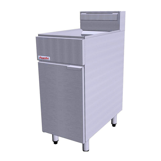
- Page 5 Model Covered in this Specification - FF18 400mm GAS FRYER (Single Tank - 18 Ltr). Gas supply connection point is located 40mm from the right hand side, 24mm from the rear and 221mm from the floor. - Flexible Hose Connection...
- Page 6 - Non UK Models: Gas Natural LP Gas / Butane Town Gas (**) Input Rating 90 MJ/hr 90 MJ/hr 90 MJ/hr (N.H.G.C.) Supply Pressure 1.13 - 2.0 kPa 2.75 - 3.0 kPa 0.75 - 1.5 kPa Burner Operating Pressure 0.90 kPa (*) 2.5 kPa (*) 0.39 kPa (*) Gas Connection...
- Page 7 Hanger unacceptable concentrations of health harmful substances in the room, the appliance is installed in. FastFri gas fryers are designed to provide years of satisfactory service and correct installation is essential to achieve the best performance, efficiency and trouble-free operation.
- Page 8 QUALIFIED SERVICE PERSON. 7. Check Supply Pressure is as shown in the ‘Specifications’ section, ‘Gas Supply 1. FASTFRI Model Fryers do not require an electrical Requirements’ tables. (Measure at the ‘Supply connection, they function totally on the gas Pressure Test Point’ (Upper - IN) on the front of supply only.
- Page 9 The following commissioning checks must be carried out before the fryer is handed over for use, to ensure that the unit operates correctly and the operator(s) understand correct operating procedure. 1. Before leaving the new installation; a. Check the following functions in accordance with the operating instructions specified in the “Operation”...
- Page 10 1. FASTFRI Fryers have been designed to provide A commercial gas fired Fryer using a single simplicity of operation and 100% safety Multi Jet Target ‘U’ burner system. protection. Available in single model type only. 2. Improper operation is almost impossible, ...
- Page 11 “LO” INDICATED LEVEL a. OIL - Carefully fill fryer tank with oil until the 'FILL-LEVEL' mark is reached. The FastFri fryer will hold 18 litres of oil (32lbs shortening). b. SHORTENING - Ideally shortening should be CORRECT LEVEL FOR FRYING MEDIUM WHEN AT FRYING TEMPERATURE, KEEP TOPPED UP pre-melted prior to putting it into the tank.
- Page 12 3. Open the access door at front of fryer to access maintain this temperature. the control panel. 5. As a safety precaution this FastFri Fryer features 4. Rotate gas control knob to the pilot position and an Over-Temp Control which will ‘Turn Off’ the hold the gas control knob depressed.
- Page 13 1. Prepare the food correctly. Prepare food in as nearly uniform pieces as possible and bring the food up to room temperature. Ensure food is free from excessive moisture and also excessive crumbing when 'breading' is done. 2. Preheat frying medium to recommended temperature for the particular food to be cooked and no higher - specially prepared frying mediums are recommended.
- Page 14 Opening the Drain Valve a. Lift the locking slide on valve handle (Fig 1) to release valve. DO NOT USE FLAMMIBLE SOLVENTS AND CLEANING AIDS ON b. While holding the locking slide in the OR IN CLOSE PROXIMITY TO THE FRYER WHILST THE FRYER IS STILL withdrawn position, rotate the handle HOT.
- Page 15 4. Carefully open the drain valve to minimise 6. Empty the fryer and rinse thoroughly with water. splashing, and take care not to overfill the Use a 1 part vinegar to 15 parts water solution to container. rinse the tank and neutralise any cleaner residue.
- Page 16 5. Cut and remove any Disconnect Gas Cut Tie Connection cable ties as required Wraps 6. Disconnect the flexi tube gas connection at the top of the Gas Control Valve. NOTE: These conversions should only be carried out by qualified service persons. All connections must be checked for leaks before re- commissioning the appliance.
- Page 17 NOTE: 1. To remove Main Injector For Town Gas application, Gas Control Valve - Burner Injectors (Qty Operating Pressure Adjusting Screw should be 9), use a ⅝” A/F replaced with the Knock Out Plug supplied in Town spanner to prevent Gas Kit and the operating pressure adjusted at the the Injector Mounting External Gas Pressure Regulator.
- Page 18 - Australia: Main Burner Injectors Ø 1.55mm Ø 0.95mm Pilot Burner Injectors 0.62 0.35 Pilot Screw Adjustment Full Out (CCW) 1½ turns out (CCW) 0.90 kPa (*) 2.50 kPa (*) Burner Operating Pressure (9.0 mbar) (25 mbar) Supply Pressure 1.13 - 2.0 kPa 2.75 - 3.0 kPa - New Zealand: Main Burner Injectors...
- Page 19 Replacement Parts List IMPORTANT: Only genuine qualified replacement parts should be used for the servicing and repair of this appliance. The instructions supplied with the parts should be followed when replacing components. For further information and servicing instructions, contact your nearest qualified service branch (contact details are as shown on the reverse of the front cover of this manual).
Need help?
Do you have a question about the FF18 and is the answer not in the manual?
Questions and answers