
Subscribe to Our Youtube Channel
Summary of Contents for Prisual E2
- Page 1 Prisual Video Conference PTZ Joystick Controller USER INSTRUCTION USE/INSTALLATION...
- Page 2 Preface Thank you very much for purchasing our products. Please be free to contact us if there is any questions or requirements. The purpose of this manual is to ensure that the user can use the product correctly to avoid danger or property damage during operation.
-
Page 3: Table Of Contents
1. P ro d u c t O v e ni i e w -------------------------------------------------------------------------------- 0 1 1.1. Product Description 1.2. Product Features 2. P ro d u c t Inte r f a c e D e si c r ip t i o n --------------- --------------- -------------- ------------------ 0 1 2.1. -
Page 4: Product Description
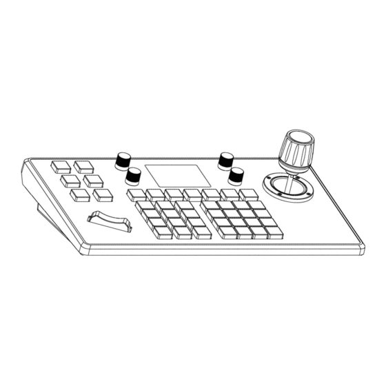
1. Product Overview 1.1 Product Description This video conference ptz joystick is made of sheet metal and scratch-resistant PC matte film, and the aluminum die-casting surface design with a powder-bottomed bottom shell. The appearance is simple and beautiful. Adopt the industrial-grade LC D panel excellent display and the characters are delicate and clear. -
Page 5: Product Connection Diagram
Corresponding function introduction Number Name Function POWER Power switch Power interface, standard 5.5/2.1 power interface DC12V DC 12V2A±10% Using for joystick upgrading Network interface, connect RJ45 for controlling Ethernet Support VISCA with full compatibility RS422 Support PELCO RS232 2.1 Product Connection Diagram 2.1.1 Network Connection (l)Network Mode: Network VISCA,ONVIF Control PTZ Camera Connection Diagram video conference camera... -
Page 6: Rs485 Connection 0
2.1.2 RS485 Connection Analog Mode: Control Common PTZ Camera Via RS485 Connection Diagram Control Output: RS485+ of PTZ camera connect to Ta of joystick controller & RS485 - of PTZ Camera Connect to Tb of Joystick controller. 2.1.3 Analog Mode: Control Video Conference PTZ Camera Via (1) Using RS422 bus connection method, the third pin Ra of the joystick controller connect to TXD IN- of the camera, the fourth pin Rb of the joystick controller connect to TXD IN+ of the camera, and the first pin Ta of the joystick controller connect to RXD IN·... -
Page 7: Connection Between Cameras 0
Joystick Joystick Camerar Camerar Controller Controller Ra <;············> TXD IN- RXD <;··········· · > TXD (2 ) Rb<;··········· ·> TXD IN+ TXD <;············> RXD Ta <;· ··········· > RXD IN GND<;············>G ND Tb <;············> RXD IN+ (2) Using RS232 connection method.The first pin RXD of joystick controller(lOpin terminal) connect to the Input Interface TXD of camera, the second pin TXD of joystick controller connect to RXD of camera,the third pin of joystick controller connect to GND of camera(also can use the standard RS232 interface(D80) of joystick controller to connect the camera.) -
Page 8: Button Function Description
3. Button Function Description O'Cll 3.1 Function Button Description [WHITE BALANCE CYCLE] Auto white balance: Click the bullon to enter the reuse function: the indoor white balance/outdoor white balance/manual white balance/ one-button white balance mode. [AUTO WHITE BALANCE] Auto white balance: Click the button to select the white balance selling. - Page 9 [EXPOSURE COMP ON] Exposure compensation ON: Click the button to turn on the exposure compensation setting. [EXPOSURE COMP OFF] Exposure compensation OFF: Click the button to turn off the exposure compensation setting. [BACKUGHT ONJ Backlight ON: Click the button to set the screen brightness gain. [BACKUGHT OFF]Backlight OFF: Click the button to set the screen brightness to the initial value display state ..
- Page 10 Serial number of the camera,can input 1-7; After adding all Camera camera information, press[Enter] button to 5ave. Select the protocol corresponding to the camera Protocol Analog Address Device Select the address code corresponding to the camera Code Select the baud rate corresponding to the camera Baud rate Added camera list, you can use the joystick to switch up and down, you can 3.
-
Page 11: Joystick & Knob Description 0
[CAMl) [CAMZ) [CAM3) [CAM4) [CAMS) [CAM6) [CAM7) Click the button to enter the corresponding device control function. Mark: 1.Click the address code to switch the camera quickly. 2.Each CAM enjoys network mode and analogue mode. 3.2 Joystick & Knob Description Output Output Output... -
Page 12: Add Analog De V Ice 0
Device List Network Device Camera : 3 Camera Protocol : ONVIF Protocol : ONVIF IP Add 192 . 168 . 0 . 245 192 . 168 . 0 . 245 IP Add Port : 80 Port : SO Protoco l : V ISCA Us er Na m e : ad m in >... -
Page 13: N Et W Ork Co Nf I G Ura T I O
Device List Keyboard Settings 1.Add Network Device Camera : 1 Z.Add Analog Device Protocol : ONVIF > 3.Device List IP Add 192.168.0.181 4.Network Attribute : Static Port : 8999 5.Lanuage : English Protocol : V ISCA 6.Button Tone : Off Address 7 .Restore Factory 8. - Page 14 2.Default user name: ad min; password: empty 3.Enter device web interface, the page display as follows: § oev,ce Management Sett,ngs ··" Addl'flS O�ate Baudrate Camera Protocol(networlc) Protocol{analog) V�UDf>) 19l.168.S.170 1259 v,s(A(UOP) VJS(A """ 12S9 192.163.S.170 VISCA(UDf>) VlS(A v&A(UOP) 19l.168.5.170 1259 v,s(A(UOP) VlS(A 1259...
-
Page 15: Web Interface Setup
6.2 WEB Interface Setup Network settings can modify the device's IP acquisition method and port parameters, as shown below: <D•- ..{;:- Dynamic Address(DHCP)(Default acquisition method):The joystick controller will request an IP address from the router automatically. After the request is successful, it will be displayed on the joystick controller's display. -
Page 16: System Reset
Upgrade function is used as the maintenance and update joystick function. After entering the upgrade page, select the correct upgrade file and click "Start". The device will automatically restart after the upgrade is completed. Note: Do not perform any operations against the device during its upgrade process, and do not power off or disconnect the network! 6.4System Reset �... -
Page 17: Export Configuration
..§ Device Management {§} Settings t& N•twork Import Upgrade (D Reset [!- Import Export @ V•nion 6.7 Export Configuration Export the related information about the current joystick controller added multiple devices, which can be exported to other joystick controller for use. g Device Management {§} Settings... -
Page 18: Fqa
0ev1te Management @settings Version H;ndw.-ire v0 0 1_190823 software V22 �_191210 (!- Import v221_191204 8 Export @) venion 7.FQA 1. When the screen displays "Connection failed", please check the device corresponding to this IP address is normally connected in the LAN. 2. - Page 20 Before attempting to connect or operate this product, Please read instructions card fully and save this manual for future u&e . • i!Ui!U.0'1.l'Hi!-Vi.U J S pe cifications are sub j ect to chan g e without notice.
Need help?
Do you have a question about the E2 and is the answer not in the manual?
Questions and answers