Table of Contents
Advertisement
Quick Links
1.0
INTRODUCTION
These instructions refer to the above models. Supplementary
sheets are attached if the unit has special options or features.
For detailed specifications, see page 4 or refer to the Data
Bulletin. All ADTE CH instruments are factory calibrated and
supplied with a label detailing the calibration. Adjustments
are normally not necessary. A simple calibration check
should be performed to verify calibration before installing
the instrument per 3.0 below.
2.0
GENERAL DESCRIPTION
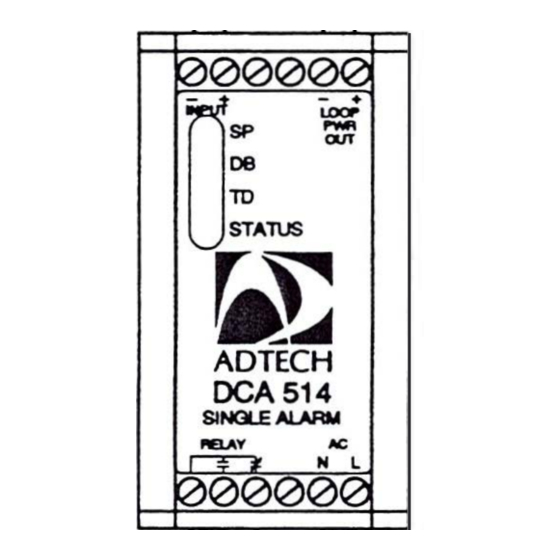
The ADTECH Model DCA 514 AC powered single alarm
accepts standard process DC current or DC voltage input
signals and provides a user configurable SPDT relay contact
output.
The basic input range is 1 to 20 mA (i.e., 4-20 mA) or any
voltage of 100 mV DC to 0-200 VDC (i.e., 1-5 VDC) the
output contacts are rated at 10 amps, 30 VDC, or 250 VAC
resistive.
An isolated 24 VDC at 30 mA DC output is provided as
standard for a loop two-wire transmitter.
An integral dual color LED provides green indication for
normal conditions and red indication on alarm independent
of relay coil power.
The alarm is furnished as standard with the relay power fail
safe F.S. (i.e., relay coil energized) regardless of high or low
alarm configurations. You may specify the relay to be non
fail-safe N.F.S. (i.e., relay coil de-energized).
The DCA 514 is supplied with adjustable dead band of 1 to
100% of input span and an adjustable time delay of 0-30
seconds is also provided as standard.
3.0
INSTALLATION
The instrument is supplied in a DIN mount general purpose
enclosure as standard. N EMA 4 or 7 are optionally available.
Installation area/location must agree with the supplied
instruments including operating temperature and ambient
conditions.
Mounting
Refer to the appropriate outline drawing for mounting and
clearance dimensions on page 4.
Electrical Connections
The wire used to connect the instrument to the control
system Input/Output should be a twisted pair(s) and sized
according to normal practice. Shielded cable is not normally
necessary (if used, the shield must be grounded at the input
negative of the ADTE CH instrument and left floating at the
sensor).
A 12 position compression terminal block is provided for 1/0
and power connection. A housing ground terminal is not
required due to non-metallic housing.
DCA 514
DC Current/Voltage Alarm
Instruction Manual
Controls
Multiturn set point (SP) control is provided to set the trip point
level on all units. Adjustable deadband (DB) control and
adjustable time delay (TD) controls are also provided as
standard.
The multiturn control(s) are accessible through the instrument
front panel and are clearly marked for ease of use.
Pin jumpers are provided to select the input, the trip mode
and relay action per tables on page 3.
4.0
MAINTENANCE
These instruments are electronic except for the relay(s)
output(s) and require no maintenance except for periodic
cleaning and calibration verification. The standard relay is
rated by the manufacturer for 100,000 10 amp operations at
30 vdc or 250 vac and 5 X 10
output( s) should be verified at user established time intervals.
If the unit appears to be mis-operating it should be checked
in place per section 6.0 or removed for a bench check per
sections 6.0 and 7.0. MOST problems are traced to field
wiring and/or associated circuits. If the problem appears to
be within the instrument, proceed to section 7.0.
5.0
CONNECTIONS
Standard connections are shown below and on the instrument
face plate, Data Bulletin or on attached supplementary
sheets.
(•J------�
INPUT SIGNAL
(-)------�
COMM
OUTPUT
NO
CONTACTS
NC
Note: See page 2 for loop power connection to a field
transmitter.
-1-
6
mechanical operations. Relay
(- )
STANDARD 24 voe
ct 30 mA DC LOOP POWER
(+ )
POWER
115 V/230 VAC
(3-94)
190-A-DCA514-B
Advertisement
Table of Contents

Related Manuals for Adtech DCA 514

Summary of Contents for Adtech DCA 514
- Page 1 You may specify the relay to be non sheets. fail-safe N.F.S. (i.e., relay coil de-energized). The DCA 514 is supplied with adjustable dead band of 1 to 100% of input span and an adjustable time delay of 0-30 (•J------�...
- Page 3 8.0 TABLES, PCB LAYOUT TABLE 1 TABLE 2 ALARM TYPE INPUT JUMPER HIGH 0-1 mA 0-10 mA TABLE 3 0-20 mA RELAY ACTION 4-20 mA FAIL SAFE (FS) 0-100 mV NON FAIL SAFE (NFS) 0-200 mV Note: FS means relay-coil normally 0-5V energized.
- Page 4 9.0 SPECIFICATIONS INPUT/OUTPUT INPUT SIGNAL e. Adjustable Time Delay: 0-30 seconds Power Supply Effect: ±0.05% for a ±10% power variation Pin Jumper Configurable g. Isolation: Input/output/power 1,500 VAC, 50/60 Hz, for AC & a. 0-1 mA DC (Zin 100 ohms) powered units.
Need help?
Do you have a question about the DCA 514 and is the answer not in the manual?
Questions and answers