Goodsmann 9920-0300-01 - 300 Watt Power Pack Manual
- Instructions (2 pages)
Advertisement
Technical specifications and warnings
TECHNICAL SPECIFICATIONS: 12 V ~ 300W
Power pack IS SUITABLE FOR USE with submersible luminaires and pumps.
For dependable performance, use genuine Goodsmann replacement parts.

Risk of Fire or Electrical Shock
- Install OUTDOORS ONLY. Use ONLY with 12 volt low voltage outdoor landscape lighting products.
- Add up all bulb wattages for a maximum total of 300 watts.
- Mount power pack at least 10 feet (3 m) from pool or spa.
- Mount power pack vertically at least 12 inches (30 cm) above ground. Do not lay on the ground.
- Mount the power pack with the back against a flat vertical wall surface. The back of the power pack must be covered by the wall.
- Plug power pack directly into an outdoor GFCI outlet with a weatherproof cover marked "wet location."
- Do not use extension cords.
- Keep a minimum of 10 feet (3 m) of wire between the power pack and the first fixture.
- Do not coil extra cable around the power pack. Leave extra cable at the end away from the power pack.
- Do not repair or tamper with cord or plug.
- Do not submerge power pack.
- Do not connect two or more power packs in parallel.
- Do not use with a dimmer.
- If house circuit breaker trips when power pack is turned on, unplug power pack from AC outlet, correct fault, and restore power. Plug power pack back into AC outlet.
- Power pack and fixtures must be installed in compliance with national and all local electrical codes and ordinances.
- If necessary to splice cable, carefully follow instructions that came with the connector you have purchased.
LED fixtures
- Do not use with fixtures that carry a Class 2 rating.
- Do not modify fixtures.
- Must follow all of manufacturers individual instructions.

Risk of Fire
- Use only CSA or UL approved low-voltage cable.
- Failure to use at least 12 gauge minimum cable or install it as directed in these instructions may result in Risk of Fire or Electric Shock.
Prepare Cable
Split one end of cable for about 3 inches (7.6 cm) being careful when splitting NOT to expose the copper wire. Then strip 5/8 inch (1.6 cm) of insulation from the end. Also, refer to strip length guide on the power pack.

Connect Cable to Power Pack
Lay power pack on a flat, stable surface and insert the stripped end of one wire under terminal clamping plate A. Then tighten the screw. Repeat this procedure for clamping plate B.

Risk of Fire
Make sure there is no wire insulation under the clamping plate,

and firmly tighten the terminal screws.
Place Fixtures and Route Cable
Lay the fixtures out where you want to locate them. Be sure they do not exceed the 300 watt rating of the power pack. Route the low voltage cable to fixtures. If there is extra cable, coil after the last fixture.
Risk of Fire
Be sure to leave a minimum of 10 feet (3 m) of wire between the power pack and first fixture.
Attach Fixtures
Turn power pack on. Attach fixtures to cable using cable connectors as shown. Place one connector on each side of the cable, then press together to lock. Prongs will pierce the cable to make contact and fixture should light up.

NOTE: When power pack is on, you may hear a hum This sound is considered normal, and does not affect the performance of the unit.
Mount Power Pack
To mount directly to a wall surface use included screws as shown, a minimum 12 inches (30 cm) off the ground. When installing the screws, the spacing between the screw centers is 2.8 in. (71.5 mm). See template for correct spacing. Hang Power Pack onto screws.

Mount Photo Eye
Mount the photo eye bracket on a wall or other solid surface with the screw provided. Snap the sensor into the bracket. Route or coil the excess wire to protect it from lawn mowers, trimmers, etc. Avoid pointing the sensor at nighttime light sources such as windows, porch lights, and street lights.

The position of the photo eye can influence at what light level the power pack will turn on in the AUTO, 4-6-8-10, and PHOTO ON TIMED OFF modes. Placing the sensor in areas receiving less sunlight at dusk (east side of house, behind trees and bushes, under a deck) will have the power pack come on earlier in the evening. Mounting the photo eye in brighter locations will have the power pack come on when it has become darker out. The location, position and orientation of the photo eye can be adjusted until the power pack turns on at the desired light level.
Protect or Hide Cable
Once all fixtures are in place and you are satisfied with their locations, cable may be covered with mulch or buried up to 6 in (15 cm) deep. Leave about 12 in (30 cm) of cable after the last fixture.
Risk of Fire or Electrical Shock
Do not coil cable around power pack.
Total bulb wattages must not exceed a maximum of 300 watts.
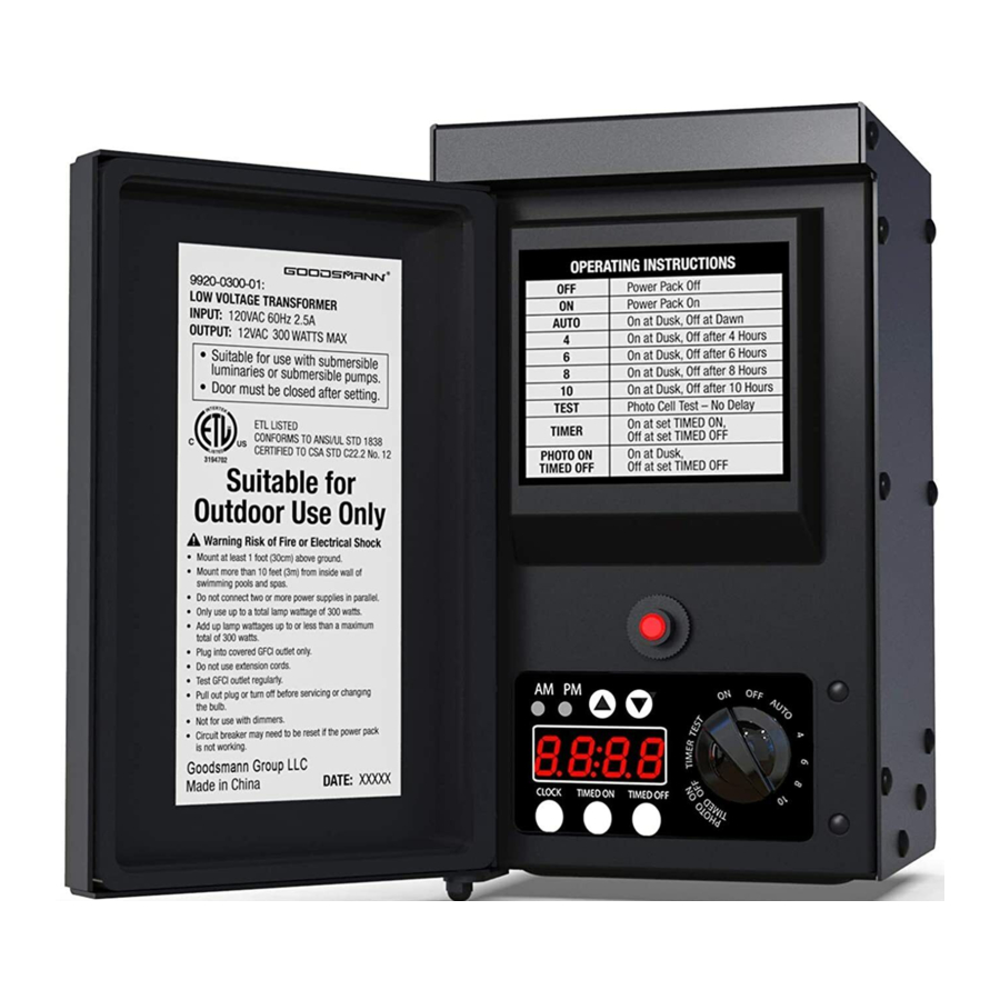
Power Pack Operation
This power pack features three automatic methods to turn on and off:
- A remote photo eye that senses the light level. There is a 15 second delay built into the photo eye to avoid being triggered by lightning or other light sources.
- A timer.
- A clock.
The power pack operation modes use these three methods in different combinations. To set the mode, open the door to the power pack controls. The LED clock display and the AM/PM indicator will be lit if the power pack is plugged in. If the LEDs are not lit, then plug in the power pack cord into the GFCI outlet.
The clock is only required for the TIMER and PHOTO ON TIMED OFF modes. The clock is ignored for any of the other modes and does not need to be set. To set the clock:
Hold down the CLOCK button while pressing either the  or
or  button. Pressing while holding down the CLOCK button will advance the displayed time. Pressing while holding down the CLOCK button will decrease the time displayed. Holding the or button down for several seconds will speed up the change in the display. Releasing the CLOCK button will set the clock time. Note the AM/PM LED indicators to get the correct time of day. This clock does NOT have a daylight savings time function. The clock time will manually need to be adjusted twice a year for those changes.
To change the operation modes of the power pack, turn the knob to point at the desired mode. The selected mode will light up.

OFF - Power Pack is off. Lights are off.
ON - Power pack is on all the time. Use this mode when installing the light fixtures to ensure a good connection.
AUTO - Power pack turns on at dusk, turns off at dawn. The lights will be on all night. There is a 15 second delay from when the photo eye determines darkness and the power pack turns on.
4 – 6 – 8 – 10 - Power pack turns on at dusk and turns off automatically after 4, 6, 8 or 10 hours. There is a 15 second delay from when the photo eye determines darkness and the power pack turns on.
TEST - Use this mode to test the photo eye and power pack operation. Covering the photo eye turns on the power pack. Uncovering the photo eye during the daytime or shining a bright light onto the photo eye will turn off the power pack. Note that there is no 15 second delay in this mode.
TIMER - The power pack turns on when the clock reaches the TIMED ON time. The power pack will turn off when the clock reaches the TIMED OFF time. This mode will turn the power pack on and off at the same times everyday regardless of how light or dark it is. The power pack and lights will be on from the TIME ON time to the TIMED OFF time.
To set the TIMED ON clock, the knob needs to be turned to TIMER, then hold down the TIMED ON button while pressing either the or button. Pressing while holding down the TIMED ON button will advance the displayed time. Pressing while holding down the TIMED ON button will decrease the time displayed. Holding the or button down for several seconds will speed up the change in the display. Releasing the TIMED ON button will set the time. Note the AM/PM LED indicators to get the correct time of day.
To set the TIMED OFF clock, the knob needs to be turned to TIMER, then hold down the TIMED OFF button while pressing either the or button. Pressing while holding down the TIMED OFF button will advance the displayed time. Pressing while holding down the TIMED OFF button will decrease the time displayed. Holding the or button down for several seconds will speed up the change in the display. Releasing the TIMED OFF button will set the time. Note the AM/PM LED indicators to get the correct time of day.
PHOTO ON TIMED OFF - The power pack turns on at dusk. The power pack will turn off when the clock reaches the TIMED OFF time. This mode will turn the power pack off at the same time every night regardless of how light or dark it is. The power pack and lights will be on from dusk to the TIMED OFF time.
To set the TIMED OFF clock, the knob needs to be turned to PHOTO ON / TIMED OFF, then hold down the TIMED OFF button while pressing either the or button. Pressing while holding down the TIMED OFF button will advance the displayed time. Pressing while holding down the TIMED OFF button will decrease the time displayed. Holding the or button down for several seconds will speed up the change in the display. Releasing the TIMED OFF button will set the time. Note the AM/PM LED indicators to get the correct time of day.
The TIMED ON clock does not work in the PHOTO ON TIMED OFF mode. It does not matter what time it is set at. Close the door to the control panel after the mode has been selected.
Replacing the Photo Eye
If the wires to photo eye are cut or broken, the photo eye can be replaced. Unscrew the connector cover from the power pack and pull the bi-pin connector out of the mating socket.

The replacement part is inserted into the socket and the cap is screwed back onto the socket to provide a water tight connection. Note that the bi-pin connector is polarized and can be inserted into the socket only one way. The photo eye operation can be tested by turning the power pack mode to TEST.
The replacement photo sensor part can be ordered by calling 972-268-6420 from 8:30 a.m. – 5:00 p.m. (CST).
NOTE: Circuit breaker may need to be reset if the power pack is not working.
Goodsmann Group LLC
2425 Mclver Lane, Suite 160
Carrollton, TX 75006 USA
www.goodsmanngroup.com
972-268-6420

Documents / Resources
References

Download manual
Here you can download full pdf version of manual, it may contain additional safety instructions, warranty information, FCC rules, etc.
Download Goodsmann 9920-0300-01 - 300 Watt Power Pack Manual
Advertisement
Thank you! Your question has been received!

Need Assistance?
Do you have a question about the 9920-0300-01 that isn't answered in the manual? Leave your question here.