
Related Manuals for ICS Schneider Messtechnik WIKA EGS80

Summary of Contents for ICS Schneider Messtechnik WIKA EGS80
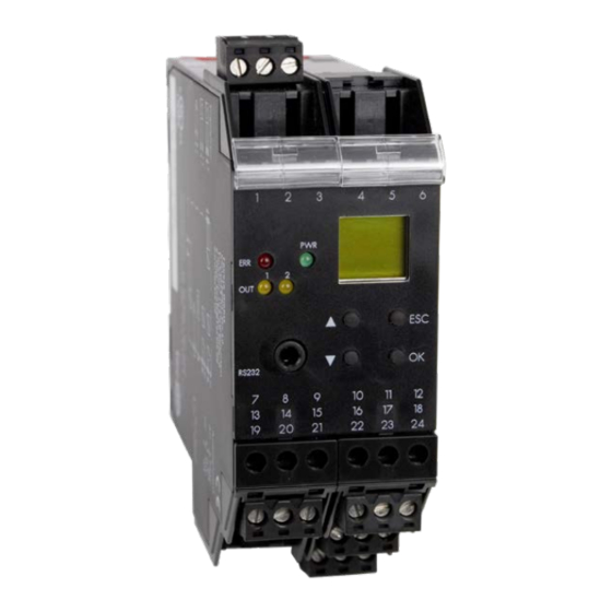
- Page 1 Operating instructions Digital limit switch, model EGS80 Digital limit switch, model EGS80...
- Page 2 With regard to the supply of products, the current issue of the following document is applicable: The general terms of delivery for products and services of the electrical industry, as published by the central association of the "Elektrotechnik und Elektroindustrie (ZVEI) e.V.", including the supplementary clause "Extended reservation of title".
-
Page 3: Table Of Contents
Trip Amplifier EGS80X002001 Trip Amplifier EGS80X002001 Table of contents Table of contents Symbols Used ..........3 Overview . - Page 4 Trip Amplifier EGS80X002001 Table of contents Relays ............. . 23 6.4.1 Operating Behaviour .
-
Page 5: Symbols Used
Trip Amplifier EGS80X002001 Symbols Used Symbols Used This symbol warns of possible danger. Failure to heed this warning may result in personal injury or death, or property damage, including destruction. Warning This symbol warns the user of a possible fault. Failure to heed this warning can lead to total failure of the device and any other connected equipment. -
Page 6: Overview
Trip Amplifier EGS80X002001 Overview Overview Range of Application The devices are used for transmitting signals between field devices and a process control system/control system. Transmitters are measuring units that provide an output signal consisting of a unit current signal (4 mA to 20 mA). A transmitter power supply provides a transmitter with power and processes the current signal. -
Page 7: Safety Instructions
Trip Amplifier EGS80X002001 Safety Instructions Safety Instructions The device may only be operated by trained professionals in a manner corresponding to this operating manual. Warning The protection of operating personnel and of the system is only ensured if the devices are used in accordance with their intended purpose. -
Page 8: Installation And Connection
Trip Amplifier EGS80X002001 Installation and Connection Installation and Connection Installation The device is constructed in protection degree IP20 and must therefore be protected from undesirable ambient conditions (water, small foreign objects). Attention The devices can be mounted on a 35 mm DIN mounting rail according to DIN EN 60715. -
Page 9: Connection
Trip Amplifier EGS80X002001 Installation and Connection Connection The removable terminals of the KF-series considerably simplify the connection and the switch cabinet assembly. They make it possible to replace devices quickly and without fault if a customer service becomes necessary. Terminals are equipped with screws, are self-opening, have a large connection area for a wire cross-section up to 2.5 mm²... -
Page 10: Connection Input (Field Circuit)
Trip Amplifier EGS80X002001 Installation and Connection 4.2.1 Connection Input (Field Circuit) The non-intrinsically safe field circuit is connected to the terminals 1 to 3. In both cases you can connect the following field devices: 1. a 2-wire transmitter 2. an active current source 24 V DC... -
Page 11: Connection Output
Trip Amplifier EGS80X002001 Installation and Connection 4.2.2 Connection Output The control circuit and the power supply are connected toterminals 7 to 24 on the device. The terminals have the following functions: • Terminals 7/8: current output (terminal 9 not used) •... -
Page 12: Field Device Communication Via Hart
Trip Amplifier EGS80X002001 Installation and Connection Field Device Communication via HART In order to set the parameters of the connected HART field device, you will require a HART communicator which you can connect to the field cables. Transmitting the HART signal via the current output of the device is not possible. -
Page 13: Display Modes And Fault Messages
Trip Amplifier EGS80X002001 Display Modes and Fault Messages Display Modes and Fault Messages In normal operation, the current measured value is indicated in the selected unit. For information on selecting the unit, see section 6.2. If the Alarm freeze (see section 6.4.3) is triggered but the device continues operating normally, a corresponding message appears in the second line of the display. -
Page 14: Editing Device Data
Trip Amplifier EGS80X002001 Editing Device Data: Parameterization Mode Editing Device Data A change in device data will change the operation of the device! Before entering new data into the device, you should ascertain that no danger to the installation will result. Warning In this manual, the parameterization of the device via the control panel is described. -
Page 15: Password
Trip Amplifier EGS80X002001 Trip Amplifier EGS80X002001 Editing Device Data: Parameterization Mode Editing Device Data: Parameterization Mode 6.1.2 Password You can protect the parameterization from unauthorized changes by means of a password (see section 6.6; at the delivery of the device, the password is inactive). If the password protection is active, you can view the different settings in the parameterization mode, but not change them before entering the password. -
Page 16: Navigation Method
Trip Amplifier EGS80X002001 Editing Device Data: Parameterization Mode 6.1.3 Navigation Method The following diagram shows the navigation method in parameterization mode using the , , OK and ESC keys: OK Rel1 Min/Max Trip ... -
Page 17: Lowest Menu Level: Select Values, Enter Numeric Values
Trip Amplifier EGS80X002001 Trip Amplifier EGS80X002001 Editing Device Data: Parameterization Mode Editing Device Data: Parameterization Mode 6.1.4 Lowest Menu Level: Select Values, Enter Numeric Values On the lowest level of the menu, you can either select one of several possible values, or enter a number for the individual parameters. -
Page 18: Unit
Trip Amplifier EGS80X002001 Editing Device Data: Unit Unit The following diagram shows the unit menu. Items from the lowest menu level are outlined in bold. The device measures in mA. Using the parameters zero point and conversion factor (section 6.3.2) it converts the measured value into the selected units. -
Page 19: Input
Trip Amplifier EGS80X002001 Trip Amplifier EGS80X002001 Editing Device Data: Input Editing Device Data: Input Input The following diagram shows the input parameters menu. Items from the lowest menu level are outlined in bold. The menu items Zero point and Conversion factor will not be shown if the unit mA is selected (section 6.2). -
Page 20: Line Monitor
Trip Amplifier EGS80X002001 Editing Device Data: Input 6.3.1 Line Monitor • If you select On for LB, an input current < 0.2 mA will be registered as a lead break (section 5). • If you select On for SC, an input current > 22 mA will be registered as a short circuit (section 5). If you wish to process the ... - Page 21 Trip Amplifier EGS80X002001 Trip Amplifier EGS80X002001 Editing Device Data: Input Editing Device Data: Input Example 1: selected unit °C, 0 °C to 200 °C is to correspond to 4 mA to 20 mA y [°C] x [mA] 9 10 11 12 13 14 15 16 17 18 19 20 -100 -150 -200...
- Page 22 Trip Amplifier EGS80X002001 Editing Device Data: Input Example 2: selected unit °C, 0 °C to -100 °C is to correspond to 20 mA to 0 mA y [°C] 9 10 11 12 13 14 15 16 17 18 19 20 x [mA] -100 -150...
- Page 23 Trip Amplifier EGS80X002001 Trip Amplifier EGS80X002001 Editing Device Data: Input Editing Device Data: Input Example 3: selected unit bar, -4 bar to 4 bar is to correspond to 4 mA to 20 mA y [bar] x [mA] 9 10 11 12 13 14 15 16 17 18 19 20 •...
-
Page 24: Linerization
Trip Amplifier EGS80X002001 Editing Device Data: Input 6.3.3 Linerization Using the parameterization software a linearization table can be saved in the device; for details of this function see On-line help. Via the operator panel you can merely switch the use of the table for the calculation of the output value on and off (On/Off). -
Page 25: Relays
Trip Amplifier EGS80X002001 Editing Device Data: Relays Relays The following diagram shows the relay outputs menu. Items from the lowest menu level are outlined in bold. From the Rel1 and Rel2 menu options, you can use the OK key to get to a menu in which you can enter individual parameters for the selected relay. -
Page 26: Operating Behaviour
Trip Amplifier EGS80X002001 Editing Device Data: Relays Alarm freeze (6.4.3) —— Delay (6.4.4) —— 0 s to 250 s 6.4.1 Operating Behaviour The switching direction can be set as Max or Min and the direction of action as Active or Passive (section 6.4). - Page 27 Trip Amplifier EGS80X002001 Editing Device Data: Relays The exact operating behaviour of the device is shown in the following diagram: Value Max – hysteresis Min + hysteresis Time Switching direction Max, mode of operation Active: energized de-energized Switching direction Max, mode of operation Passive: energized de-energized Switching direction Min, mode of operation Active:...
-
Page 28: Trip And Hysteresis
Trip Amplifier EGS80X002001 Editing Device Data: Relays 6.4.2 Trip and Hysteresis When entering the values for Trip and Hysteresis please note: • Both values are to be entered in the units, which were selected under Units (section 6.2). • You can enter values ... - Page 29 Trip Amplifier EGS80X002001 Editing Device Data: Relays The following diagram shows the operating behaviour for the trip mode Max, operating mode Active. Value Trip point Max Max – hysteresis Time Switching direction Max, mode of operation Active, with delay energized de-energized Delay Delay...
-
Page 30: Current Output
Trip Amplifier EGS80X002001 Editing Device Data: Current Output Current Output The following illustrations show the current output menus. Items from the lowest menu level are outlined in bold. Information about relay outputs see section 6.4. Output —— Rel1 Rel2 Iout ——... -
Page 31: Characteristic
Trip Amplifier EGS80X002001 Editing Device Data: Current Output Start value —— 6.5.3 End value —— 6.5.3 Inverted (6.5.1) —— Inverted Normal 6.5.1 Characteristic With the parameters Start value and End value establish a sub-range of the input signal as the measuring range of the application (section 6.5.3). - Page 32 Trip Amplifier EGS80X002001 Editing Device Data: Current Output Characteristic Start value End value Linear Linear overrange converted into converted into underrange up to up to 0 mA to 20 mA 0 mA 20 mA 0 mA 20.5 mA 4 mA to 20 mA 4 mA 20 mA 3.8 mA...
-
Page 33: Fault Current
Trip Amplifier EGS80X002001 Editing Device Data: Current Output 6.5.2 Fault Current The following table shows the current output in the event of a fault, depending on the characteristic. Setting 0 mA to 20 mA 4 mA to 20 mA NE43 4 mA to 20 mA Up/Down 21.5 mA... -
Page 34: Service
Trip Amplifier EGS80X002001 Editing Device Data: Service Service The following diagram shows the service parameter menus. Items from the lowest menu level are outlined in bold. Service —— Password (6.1.2) —— Language —— DE (German) ENG (English) Reset (see below) ——... -
Page 35: Default Settings
Trip Amplifier EGS80X002001 Editing Device Data: Default Settings Default Settings Menu Parameter Default setting Separate value Main menu Unit Input Line monitor On LB/On SC Zero point 4.000 mA Conversion factor 0.100 Linearization Smoothing Output Rel1 Min/Max (= switching direction) Trip 16.00 mA Hysteresis... - Page 36 Trip Amplifier EGS80X002001 Editing Device Data: Default Settings Menu Parameter Default setting Separate value Fault current Start value 0.000 mA End value 20.00 mA Inverted Normal Service Password Language...
- Page 37 Trip Amplifier EGS80X002001 Notes...
- Page 38 Trip Amplifier EGS80X002001 Notes...
- Page 39 Trip Amplifier EGS80X002001 Notes...
Need help?
Do you have a question about the WIKA EGS80 and is the answer not in the manual?
Questions and answers