Table of Contents
Advertisement
Quick Links
Advertisement
Table of Contents

Summary of Contents for avantor VWR VC100
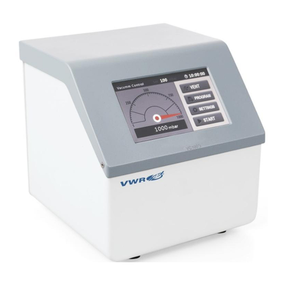
- Page 1 Instruction Manual ® CONTROLLER VACUUM VC100 Version01 Issue 3/ 10/2023...
- Page 2 Legal address of Manufacturer United States VWR International LLC 100 Matsonford Rd Radnor, PA 19087 +1 800-932-5000 www.vwr.com Country of Origin China Version01 Issue 3/ 10/2023...
-
Page 3: Table Of Contents
Table of Contents SAFETY PRECAUTIONS....................4 PRODUCT OVERVIEW ....................5 ......................5 2.1 S COPE OF APPLICATION 2.2 T ......................5 ECHNICAL PARAMETERS ........................6 2.3 C OMPONENTS OPERATING INSTRUCTIONS..................7 ....................7 3.1 O PACKAGE INSPECTION ..........................8 3.2 O PERATION MAINTENANCE...................... -
Page 4: Safety Precautions
1. Safety Precautions Caution! • Please carefully read the manual before operating the product, and observe the specifications on safe operation. • Ensure that only trained staff operates this product. Ground protection for safety! • Ensure that the power socket has been properly grounded before operating the product •... -
Page 5: Product Overview
2. Product overview 2.1 Scope of application • The instrument is designed for the application environments with dedicated independent power supply, such as schools, laboratories and factories. It is applied to control the vacuum level of the vacuum system with gas as the medium in the environments, under the circumstance as below. -
Page 6: Components
Materials in co n t a c t wi t h PTFE, PP, silica gel and ceramics steam Steam temperature 5℃-40℃ External dimension 189mm×207mm×193mm WxDxH Weight 4.0kg Input power supply AC110—240V, 50Hz/60Hz 10℃-40℃ , ≤80%RH ,the altitude does not exceed Working temperature 2000 meters Pollution levels... -
Page 7: Operating Instructions
power supply to the entire unit. switch Communication Communication interface Pump interface Connects the vacuum pump Connects with air or inertia gas if necessary. Air vent Connects the load, such as revolving evaporator. Load interface Power output Provides power supply to vacuum pump. socket Table 2 3. -
Page 8: Operation
3.2 Operation 3.2.1 Instrument preparation • The instrument should be place on a stable surface and well ventilated without any flammables or explosives. • Ensure that the label indicated the correct voltage before connecting the device to power supply. • Ensure that the power socket is grounded properly. - Page 9 icon changed to , gently touch it again to stop the control program. Table 4 Note: ‘PROGRAM’ and ‘ SETTINGS’ buttons cannot be operated if the control program starts.
- Page 10 3.2.3. Instrument configuration Gently touch the "SETTINGS" button to pop up the password soft keyboard, enter the password (the default initial password is 6666), then press “enter” key, confirm the password is correct and then pop up the setting interface, as shown in the figure below. Fig.
- Page 11 3.2.4. Operation mode selection and configuration Click the “Program” button to pop up the program selection interface as shown in the following figure. Fig. 3.2.3 Click “ Vacuum control” in the “ Function” section to choose the single- point control operation mode, click “Program” to select the program operation mode.
- Page 12 Name Function Introduction Set the vacuum value within a range of 1 - local atmospheric Set vacuum(mbar) pressure (P0) Hysteresis value affects the pressure fluctuation range and Hysteresis(mbar) the ON/OFF frequency of vacuum pump. Setting range 1-300mbar Time(min) Time can be set within a range of 0-5999min Table 6 After setting the parameters, click “OK”...
- Page 13 (1) Program selection Name Function introduction Open Select the program number Hysteresis value affects the pressure fluctuation Hysteresis(mbar) range and the ON frequency of vacuum pump Setting range 1-300mbar Table 7 After setting the parameters, click “OK” key to enter the program operation interface as shown in the following figure.
- Page 14 (2) Program editing Click the “Edit” button in the “program selection interface” to pop up the program editing interface as shown in the following figure. Program editing area Program selection button Fig. 3.2.7 Name Function introduction Sequence No. of program execution Time(min) Timing time, set within a range of 0-5999min Set the vacuum value within a range of 1 - local...
-
Page 15: Maintenance
will be skipped to the next control program. 3.2.5. Ventilation Gently touch the “VENT” button to vent air and lift it to stop venting. 4. Maintenance Proper maintenance and operation of the instrument in good working state can extend its service life. Keep the instrument dry and clean in routine operations. -
Page 16: Failure Diagnosis
5. Failure diagnosis The advanced production technology and testing methods are used for rigorous testing before delivery, to ensure good reliability. In service, the common failures are generally caused by improper operation or setting. If the errors cannot be handled properly, please record the error phenomenon and notify the local dealer, or contact us directly. -
Page 17: Warranty Policy
Technical service Web Resources Visit the VWR website at vwr.com for: • Complete technical service contact information • Access to the VWR Online Catalogue, and information about accessories and related products • Additional product information and special offers Contact us for information or technical assistance contact your local VWR representative or visit www.vwr.com. - Page 18 Equipment disposal This equipment is marked with the crossed out wheeled bin symbol to indicate that this equipment must not be disposed of with unsorted waste. Instead it's your responsibility to correctly dispose of your equipment at life cycle -end by handling it over to an authorized facility for separate collection and recycling.
- Page 19 Our offices in North America United States VWR International, LLC 100 Matsonford Road Building One Suite 200 Radnor, PA 19087 Tel.: +1 800 932 5000 Email: vwrcustomerservice@vwr.com Canada VWR International 2360 Argentia Road Mississauga, Ontario L5N 5Z7 Tel.: +1 800 932 5000 Email: canadainfo@avantorsciences.com Mexico VWR International S.
Need help?
Do you have a question about the VWR VC100 and is the answer not in the manual?
Questions and answers