
Summary of Contents for Beam 250
- Page 1 Beam 250 moving head light User manual (RDM, color display, touch operation) Please read the instructions carefully before use...
- Page 2 Catalogue Chapter 1 Precautions and Installation ..................Maintenance ........................Statement .......................... Product Precautions ......................Fixture installation ......................Chapter 2 Panel Operation ......................Overview ..........................Menu operation ........................ Function Menu Description .................... Set address ........................ Set working mode ....................Display setting ......................Chapter 3 Channel Description ......................
-
Page 3: Chapter 1 Precautions And Installation
Chapter 1 Precautions and Installation 1. Maintenance The fixture shall be kept dry to avoid working in a humid environment. Intermittent use will effectively prolong the service life of the fixture. In order to obtain good ventilation effect and lighting effect, pay attention to cleaning the fan, fan mesh and lens frequently. - Page 4 when the bulb is used, the change of power supply voltage shall not exceed ± 10%. If the voltage is too high, the life of the bulb will be shortened. If the voltage is too low, the light color of the bulb will be affected. After the power is cut off, it takes 20 minutes for the lamps to be fully cooled before being powered on again To ensure the normal use of this product, please read this instruction carefully.
- Page 5 necessary to use a safety rope to pass through the support frame and the lamp handle for auxiliary hanging to ensure safety and prevent the lamp from falling and sliding. During the installation and commissioning of fixtures, pedestrians are not allowed to pass under them.
-
Page 6: Chapter 2 Panel Operation
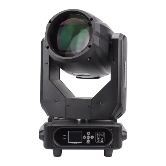
Chapter 2 Panel Operation 1. Overview The schematic diagram of the fixture panel is shown in Figure 3. The title above shows the lamp name, and the status bar below shows the signal, bulb status, and fault of the current lamp ("ERR" is displayed when the fault information is not viewed, otherwise "NOR"... - Page 7 Application value: When the data is set by pressing the "Up" or "Down" button, and then press the "Apply" button at the bottom left corner, the value will be sent to the lamp immediately, but the value is not saved. Save the value: at any time, click the "OK"...
-
Page 8: Chapter 3 Channel Description
Channel mode: different channel modes can be selected circularly; fixture reset: reset all motors. 2. Set fixture working mode The fixture supports four operation modes (DMX mode, self-propelled mode, voice control mode and scene mode) 3. Panel display setting Fixture support Chinese English bilingual, upside down display Chapter 3 Channel Description CHANNEL Function... -
Page 9: Chapter 4 Common Faults And Precautions
Check whether the bulb has reached its service life, and replace it with a new one; Check whether the circuit between the bulb and the lamp lighter leaks, falls off or has poor contact; Replace with a new lamp lighter. 2. The beam appears dim... - Page 10 Possible causes: The bulb has been used for a long time or the light path is not clean. The treatment is as follows: Check whether the bulb has reached its service life, and replace it with a new one; Check whether the optical components or bulbs are clean and whether there is dust on the bulbs and other optical components.
- Page 11 Add signal amplifier and 120 ohm terminal resistor; 6. The fixture cannot be started Possible causes: the power line is poor, and the treatment is as follows: Check whether the fuse on the power input socket is fused, and replace the fuse; Poor line contact caused by vibration of lamps during long-distance transportation Check the input power supply, computer board and other plug-in devices.
- Page 12 10 hours, and the interval between the continuous starting of the fixture should not be less than 10 minutes, otherwise it will not be triggered normally due to the overheat protection of the bulb; The closing time of switching valve shall not exceed 5 minutes. If it is necessary to turn off...
- Page 13 When the fixture is controlled by DMX, but the RDM cannot search the fixture, check the signal amplifier first, and then check whether there is a poor contact between the 2 and 3 lines of the signal line.
Need help?
Do you have a question about the 250 and is the answer not in the manual?
Questions and answers