Advertisement
GSM
click
™
1. Introduction
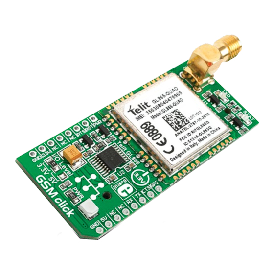
GSM click
is an add-on board in mikroBUS
™
form factor. It's a compact and easy solution
for adding GSM/GPRS mobile phones standard
to your design. It features a GL865-QUAD
GSM/GPRS module, a TXB0106 6-bit
bidirectional voltage-level translator and a
SIM CARD socket. GSM click
communicates
™
with the target board microcontroller via
seven mikroBUS
lines (RX, TX, INT, PWM,
™
CS, RST and AN). The board is designed to use
3.3V and 5V I/O voltage levels. A LED diode
indicates the presence of power supply.
2. Soldering the headers
Before using your click
board, make sure
™
to solder 1x8 male headers to both left
and right side of the board. Two 1x8 male
headers are included with the board in
the package.
2
Turn the board upside down so that
bottom side is facing you upwards. Place
shorter parts of the header pins in both
soldering pad locations.
™
1
3
Turn the board upward again. Make sure
to align the headers so that they are
perpendicular to the board, then solder the
pins carefully.
3. Plugging the board in
Once you have soldered the headers your
board is ready to be placed into desired
mikroBUS
™
socket. Make sure to align the
cut in the lower-right part of the board
with the markings on the silkscreen at
the mikroBUS
socket. If all of the pins are
™
aligned correctly, push the board all
the way into the socket.
4. Essential features
GSM click
with it's Telit GL865-QUAD IC is
™
ideal for mobile devices. It features GSM/GPRS
protocol stack 3GPP (release 4 compliant) and
supports GSM/GPRS 850/900/1800/ 1900
MHz Quad-band frequency. Additional features
such as integrated TCP/IP protocol stack
(including UDP, SMTP, ICMP and FTP), serial
multiplexer, remote AT commands and many
more, extend the functionality of the board.
click
™
BOARD
www.mikroe.com
GSM click Manual
ver. 1.01c
0 100000 026595
Advertisement
Table of Contents

Summary of Contents for MicroElektronika GSM click
- Page 1 ™ socket. Make sure to align the www.mikroe.com SIM CARD socket. GSM click communicates cut in the lower-right part of the board ™ with the target board microcontroller via with the markings on the silkscreen at...
- Page 2 6. SMD Jumper 5. GSM click board schematic ™ +3V3 ANTENNA PWRMON GPIO2 MISO There is one zero-ohm SMD jumper J1 which is MOSI TX_LED BC846 +3.3V used to select whether 3.3V or 5V I/O voltage MIKROBUS DEVICE CONN. 100K level is used.
Need help?
Do you have a question about the GSM click and is the answer not in the manual?
Questions and answers