
Summary of Contents for Dürr Dental XR 24 Easy
- Page 1 Dürr Dental XR 24 Easy Installation and Operating Instructions 9000-600-84/30 ...
-
Page 3: Table Of Contents
Content 12. Start-up and first use ������������� 20 12�1 Checktemperatureofthedevelo- perandcarryoutcommissioning test������������������������ 20 13. Transport����������������������� 21 13�1 Removeinletanddrainagehoses�� 21 13�2 Protectionfromdamage �������� 21 Important Information 1. General ������������������������� 4 1�1 NoteonConformity ������������� 4 1�2 GeneralNotes ����������������� 4 1�3 ApplianceDisposal�������������� 4 1�4 Notesonmedicalproducts � ������� 4 14. Operation�����������������������... -
Page 4: Important Information
•ThetranslationoftheseInstallationand Important OperatingInstructionshasbeencarriedoutin goodfaith�DürrDentalwillnotacceptany Information claimsarisingfromincorrecttranslation�The enclosedGermanversionoftheseInstallation andOperatingInstructionsisthefinalrefe- 1. General rence-incaseofdoubtcontactthemanufac- turerortheiragent� 1.1 Note on Conformity •Anyreprintingofthetechnicaldocumentation, Thisproducthasbeentestedforconformityac- inwholeorinpart,issubjecttopriorapproval cordingtotheappropriatedirectivesaslaid ofDürrDentalbeinggiveninwriting� downbytheEuropeanUnionandhasbeen •Retainthepackagingforpossiblereturnofthe foundtoconformtoalltherequired producttothemanufacturers�Onlytheorigi- specifications� nalpackagingprovidesadequateprotection duringtransportoftheunit� 1.2 General Notes Shouldreturnoftheproducttothemanufac- •TheseInstallationandOperatingInstructions turersbenecessaryduringtheguaranteeperi- formanintegralpartoftheunit�Theymustbe od,DürrDentalacceptsnoresponsibilityfor keptclosetotheunitatalltimes�Preciseob- damageoccurringduringtransportwherethe servanceoftheseinstructionsisaprecondi- originalpackagingwasnotused! tionforuseoftheunitfortheintendedpurpo- Ensurethatthepackagingiskeptoutofthe seandforitscorrectoperation� reachofchildren� Newpersonnelmustbemadeawareofthe contents,andtheyshouldbepassedontofu- 1.3 Appliance Disposal tureoperatingstaff�... -
Page 5: Medical Products
1.5 Notes on EMC and Whereanydoubtsremainconcerningthesa- fetywhenconnectingtootherunitsthenthe medical products operatorisobligedtoascertainthatsuchcon- Medicalproductsshouldbetreatedwithrespect nectioncaninnowayaffectthesafetyofope- whenitcomestoelectro-magneticcompatibility rator,patientorotherstaffbyreferringtothe andspecialsafetymeasuresmustbetaken� manufacturerorafullyqualifiedandcompe- NotesonEMCformedicalproductscanbe tentexpert� foundintheinformationobtainedwithorderno� 9000-606-67/30ortheinformationonthe 2. Safety Internet(www�duerr�de)inthedownloadareafor technicaldocumentation� 2.1 General Safety Notes 1.6 Correct Usage Thisappliancehasbeendesignedand constructedbyDürrDentalthatanydangerari- TheX-rayfilm-developing-machineXR 24 Easy singfromcorrectusageisvirtuallyimpossible� isdesignedfortheautomaticdevelopmentof Inspiteofthis,wefeelitisourdutytomention extraoralandintraoralX-rayfilmsofformats2x thefollowingsafetymeasuresinordertopre- 3cmto24 x 30 cm,accordingtotheDürrlistof ventanypossibledanger� recommendedfilms� •Whenusingthisappliancealllocalandrele- vantregulationsmustbeobserved! 1.7 Incorrect usage Convertingormodifyingtheapplianceinany Anyuseofthisappliance/theseappliancesabo- wayisstrictlyprohibited�Insuchcases,any veandbeyondthatlaiddownintheInstallation andallguaranteesimmediatelybecomeinva- andOperatingInstructionsisdeemedtobein- lid�Theoperationofmodifiedappliancescan... -
Page 6: 2�2 Electricalsafetyinstructions
3. Warnings and Symbols 2.2 Electrical safety instructions •Theappliancemayonlybeoperatedusinga Intheoperatinginstructionsthefollowingwar- correctlyinstalledpowersocket� ningsandsymbolshavebeenused: •Beforeconnectingtotheelectricitysupplythe Information and/or mandatory re- appliancemustbeinspectedandchecked gulations or prohibitions for the thatthesupplyvoltageandthesupplyfre- prevention of personal injury or sub- quencycorrespondtothatofthelocalelectri- stantial property damage calsupply� Informationand/orinstructionsorprohi- •Beforeinitialuseandstart-uptheappliance bitionsregardingpersonalsafetyorex- andallsupplylinesmustbecheckedforany tensivematerialdamage� signsofdamage�Damagedsupplylinesand connectionsmustbereplacedimmediately� Warning - dangerous electrical voltage. •Nevercomeintocontactwithpatientsand openplug-inconnectionsontheapplianceat Eachmorning-openthewatertap thesametime� •Whenusingtheapplianceobservealltherele- vantelectricalsafetyprocedures� Eachevening-turnwatertapoff Mainpowersupply-On Mainpowersupply-Off YellowLED-warming-upphaseof appliance GreenLED-Device readyforoperation Afterapproximately20minutes,theset temperaturehasbeenreachedandthe yellowandgreenLEDSlightup� OrangeLED... -
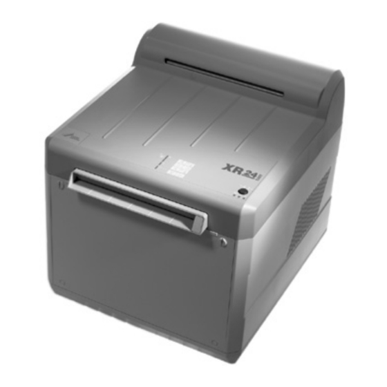
Page 7: 3�1 Modelidentificationplate
3.1 Model identification plate Amodelidentificationplate(fig�1)canbefound, afterremovingthetopcover,totherightbelow themainpowerunit� Asecondmodelidentificationplatecanbe foundtotherearofthemachine,neartothe powercord� OrderNo�/ModelNo� SerialNo� Observeaccompanyingdocumentation! Disposeofcorrectlyinaccordancewith EU-guidelines(2002/96/EG-WEE) ... -
Page 8: Delivery Contents
4. Delivery Contents 4.2 Disposable materials DürrAutomaticXR Thepartslistedasspecialaccessories developerandfixerconcentrates arenotpartofthestandardscopeof for2applications�������������������������CXB140C99�� deliverybutcanbeorderedseparately� Universal Cleaner, for cleaning X-ray film developer XR 24 Easy roller sets, 2 x Pack ..... CCB600C55.. Model 1700-10 (230VAC,50/60Hz) SpraycleanerWR2000,for transportrollersets,6xPack � ����� CCB800C55�� DürrCleaningInstructions������� 9000-600-19/01 AccessoriesI������������������������������� 1700-001-00 DÜRR Cleaning film, clear x 100 ... 1410-007-00 Starterpack � ������������������������������� 1702-050-00 4.1 Special accessories Thefollowingpartsarenotincluded�... -
Page 9: Technical Data
5. Technical Data 5.1 X-ray film developer XR 24 Easy Model 1700-10 Voltage 230/1~ Electrical frequency 50/60 Power output Heat output Bath heating Drying Warm-up time 0�5°C/min ca�20 Film processing ca�6 time Bath agitator for l/min ca�1,5 developer Bath agitator for l/min ca�2,0 fixer Water circulation l/min rate Water pressure, min.. Water pressure, max. Tank volume 5each Developer, Fixer Fuse type IP20 Protection class Medical device Surge voltage category Declaration of conformity... -
Page 10: Functional Diagram Xr 24 Easy
6. Functional Diagram XR 24 Easy 1 2 3 A 1 Filmfeed 2 Startflap 3 Rollerset-filmfeed 4 Rollersets developer/fixer 5 Cover 6 Rollerset-water 7 Waterbathlevelsensor 8 Filmoutlet 9 Rollerset-dryer 10 Driveshaft 11 Thermofusing 12 Dryerheating 13... -
Page 11: Functional Description
7. Functional description •Themotor(15)operatesthedriveshaft(10) viatherollerbelt(14)�Thetoothedcogson 7.1 Brief details therollersetsaredirectlyconnectedtothe wormscrewcogsofthedriveshaft�Thiscon- TheX-rayfilmdeveloperXR 24 Easyisfitted nectionservestorotatetherollersoftheroller withaStart-Stop-Automatic� setsinordertotransportthefilmthroughthe Theapplianceonstand-bymodewillstartauto- variousprocesssteps� maticallyontheinsertionofafilm� Thevariousfilmprocessingstepsare: Thefilmwillbetransportedthroughboththede- 1�Filminsertionslot,2�Developerbathand veloperandfixerbaths,andthenbecarried Fixerbath,3�Waterbath,4�Dryer� throughthewaterbathtothedryingzone� •Theventilationfan(13)servestoextractair� Approximately1minuteafterthefilmrun Onitswaytothedryingzonetheairiswar- throughprocesshasended,themachineauto- medbytheheatingsystem� maticallyswitchesintostand-bymode� Theheatingtemperatureissettoastationary value� 7.2 Warm-up stage •Therotarypump(16)activatesthecirculation Afterswitchingonthemainpowersupply(A)the ofthedeveloperandfixerbaths�Duringthe yellowLED(B)lightsup�Aslongastheyellow operationalcyclethecapillarytubecontroller LEDisdisplayed,thetemperatureinthedevelo- (18)regulatesthetemperatureofthebath(s)� perbathandthefixerbathisbeingraised� Afterinsertionofthefilmthefilmfeedflap(2) Heatingiseffectedbyaheatcartridgeinthe closes�Afurtherfilmcanbeinsertedassoonas processheater(19)�Thetemperature,factory- theorangeLED(D)switchesoff�... -
Page 12: Set-Up
Mounting 8. Set-up 8.1 Room for set-up •TheXR 24 Easydevelopermayonlybeope- ratedinaclean,dryandwell-ventilatedroom� •Roomtemperaturemustnotfallbelow+10 °C inwinterandmustnotexceed+28°Cin summer� Neverexposethemachinetodirect sunlight!Dangerofthechemicalsover- heatingorpre-exposureoffilm materials� •Theroomchosenforset-upmusthaveac- cesstoawaterconnection(watertap)(28) R3/4"withpipeanti-vacuumdevice,waste waterdrainage(29)withaeration(anti-odour) viaplasticsiphonandanelectricalsafetyso- cket(27)�Havingasinkforwashingnextto thedeveloperisalsorecommended� The water tap (28) and electrical safety so- cket (27) must be easily accessible to the operating personnel. •Westronglyrecommendthatset-upofthe XR 24 Easyiseffectedinadarkroom� Iftheappliancecannotbesetupinadar- kroom,thenadaylightcover(24)(DL 24or DL 26)mustbefitted� •Whenoperatinganappliancewithdaylightco- ver(25)pleasenote: Do not store films in the vicinity of a room used to take X-rays! Whenstoringfilmmaterialinthefilmde- pot(26)ofadaylightcoverthereisthe dangerofpre-exposure�Thepre-expo- surecanbecausedbytheX-ray appliance� Ifnecessaryimposeaseparatingwallorbarrier equippedwithleadprotectionbetween� ... -
Page 13: 8�2 Unpacktheappliance
8.2 Unpack the appliance •Cuttheplastictiesfromthepackaging�Lift theboxupwardsandremove� •Removeallsmallparts� 8.3 Prepare set-up location •Theapplianceshouldbeset-uponastable, flatandsuitablylargeworkingsurfaceatan appropriateheightforworkingat� •Inordertohaveaccesstothehosesthewor- kingsurfaceshouldhaveatleastoneopening ofca�10 x 7 cm� •Takeintoaccounttheneedforadditional spaceforservicingandforsufficientventilati- onfortheappliance: At least 10 cm free space behind, appro- ximately 50 cm free space to the left and right. Leaveenoughspaceatthefrontincaseaday- lightcover(25)istobeused� 8.4 Set-up •Lifttheapplianceatthesidesandplaceinits set-upposition� •Thedistancebetweenthemachineandthe waterconnectionorthewaterdrainandthe electricalsafetysocketshouldbemaximum 1�5m� •Setuptheappliancesothatithasaslighttilt, ca�0�3 °tothefixerbath(fig�7)� Adjustthefeetoftheappliance(30)usingthe spannerprovided(31)asrequired� ... -
Page 14: Installation
9. Installation 9.1 Water connections •Checkthatclean,clearwaterflowsfromthe watertap(28)� When installing for the first time make sure the connection is allowed to flow and rinse first! •Turnoffthewatertap(28)� •Connectthe90°elbowpiece(34)tothewater tap(28),mountingthefinefilter(33)(arrowin directionofflow)andthedoublenipplepiece (32)atthesametime� Becausethequalityofwatervariesfrom regiontoregionwestronglyrecommend fittingafinefilter(33)(orderno�1700- 008-00)betweenthewatertap(28)and thewaterhose(35)� Thefinefilter(33)protectstheflowregu- latorinthewaterintakevalveoftheap- pliancefrombecomingdirty� •Check,whetherthecoarsefilter(35a)and bothseals(35b)arepresentinthethreaded pipefittingsforthewaterhose(35)� •Connectthewaterhose(35)tothewaterin- flow(36)oftheappliance(threadedpipefitting withcoarsefilter)andconnecttodoublenipp- lepiece(32)� 9.2 Waste water connections •Thewastewaterconnectionmustincludea siphontrap� •Laythewastewaterhose(37)withaconstant inclinetothesiphontrap� Shortenthewastewaterhosetothecorrect length� ... -
Page 15: From Developer And Fixer
Problems with the waste water flow can be avoided by keeping the following in mind when laying the waste water hose: Do not let the hose hang! Avoid squeezing or reducing the pressure on hose! •ApplyasmallamountofUHU-Plastorsimilar totheoutsideofthehoseendofthewaste waterhose(37)� •Screwthescrewsocket(38)ontothewaste waterhose(37)� •Fastenthedrainagehoseontotheconnector ofthesiphontrap(40)withhoseclamp(39)� •Fixthewastewaterhosetothewallusing hoseclamp,screwsanddowels� 9.3 Waste water hose connection from developer and fixer •Placethe10l-collectortanks(43)fordevelo- per(blacklevelindicatormarker)andfixer(red levelindicatormarker)belowtheappliancein aclearlyvisiblepositionandfreefromthe possibilityoftilting�Seealsofig�11� •Laythehose(41)withconstantincline •Shortenthehosestothecorrectlength� max. 3 cm •Slidethehosefordeveloper(blackmarking) throughtheopeningoftheblackcover(42)� (Fig�13�) •Screwthecover(42)ofthecollector(43)for developerontightly� •Fixthehoseforfixer(redmarkings)inthe samewaytothefixercollector� As soon as the level in the collector reaches the level indicator markings (43a) then the collector must be emptied. Danger of spilling! ... -
Page 16: Commissioning
9.4 Cleaning the Appliance before Commissioning •Removethecoverandthetransportationsa- fetydevices(2styrofoamstrips)� •Openthegreencatch(44)andlockingde- vices(45)� •Swingtherollersetforthedryer(9)towards therear� •Removerollersets(3),(4)and(6)� •Liftthebath(23)out� •Cleantherollersets,bathandtanksusinga dampsponge� •Whenfinishedreplacethepartsinreverse order� ... -
Page 17: Electrical Connection
•Replacethesidecovers(46) (ventilationslotstorear)� •Placethefrontpanelwiththelabel XR 24 Easyinplaceandsecurewiththree cross-headedscrews(48)� Donotmixupthefrontandrearpanels� Onlythefrontpanelhasthenecessary boredholesforattachingthedaylight cover� •Passthequick-releasecatches(46a)through theholesprovidedonthefrontpanel� •Similarlyfixtherearpanelinplacewiththe threecross-headedscrews(47)� •Fillchemicals,see14�4�3 andinstallrollerset,see14�4�4� 10. Electrical connection This appliance is designed for use with supply voltage of 230 V, 50/60 Hz (see mo- del identification plate, fig. 1). Before connection of the main po- wer cable it is important to check whether the required voltage is available, otherwise the appliance can be damaged. Use the Dürr mains cable supplied. The appliance may only be connected to the mains supply when all panels and the cover are correctly in place. •Connectthepowerplug(49)intotheappli- anceandintothemainpowersocket� ... -
Page 18: Circuit Diagram Type 1700-10
11. Circuit diagram type 1700-10 ... -
Page 19: 11�1 Keytocircuitdiagram
11.1 Key to circuit diagram Name of appliance or part PCB connections B1 Thermicswitchforbathheating X1�1-X1�3N B2 Levelsensorforwaterbath X1�4 Rollerdrivemotorcapacitor F3 Temperaturecontrolfusefordryer X1�5 Capacitortofanmotor H1 Gl=LED(red) X1�6 LEDred H2 Gl=LED(green) X1�7 solenoidvalveforwater, H3 Gl=LED(yellow) drivemotor, M1 Rotarypumpforbath dryerheater, M2 Dryer dryer M3 Drivemotorforrollers X1�8 NC=notused R1 Bathheating X1�9... -
Page 20: Start-Up And First Use
12. Start-up and first use 12.1 Check temperature of the de- veloper and carry out commis- sioning test •Switchtheunitonandwaitforthewarm-up stageofthedeveloperbath,seealso "13�1Morningsorbeforesurgerystart-up"� •Tocheckthetemperatureofthedeveloper, switchofftheunit� •Unplugatthemainsandremoveallpower� •Closethewatertap� •Removethecover� •Measurethetemperatureofthedeveloper (frontlefttoadepthofca�20cm)� Thedevelopertemperaturemustbe,accor- dingtothefilmlist,e�g�+28°C+/-0�5°C� •CarryoutaCommissioningTestaccordingto nationalregulations� ... -
Page 21: Transport
13. Transport Beforetransportofthedeveloperpleasenote thefollowingpoints: Thedevelopermayonlybetransported withcompletelyemptytanksandbaths� Dangerofmixingofchemicals! Dangerofspillageorleaks! •Drainallchemicals,see 14�4�1 •Cleanthetanksandrollersets,see14�4�2 13.1 Remove inlet and drainage hoses •Unscrewthewaterhose(35)fromtheunitand fromthewatertap(8)� •Removethedrainagehose(37)� •Loosenthehosefromthecollector(43)for developerandfixer�Becarefultopreventany spillageorleakageofchemicals� 13.2 Protection from damage •Protectthedeveloperfromanymechanical pressureanddamage •Ensurethattheapplianceduringtransport cannotmovewithinthepackaging� •Informtransportpersonnel� ... -
Page 22: Operation
A D C B 14. Operation 14.1 Mornings or before surgery start-up Beforeoperatingtheappliancepleasenotethe followingpoints: • Openthewatertap� •Switchonmainpowersupply(A)� The developer must never be opera- ted without roller sets! • Duringthewarming-upphasetheyellow Ifrollersetsaremissingthenthedevelo- LED(B)lights� perandfixerfluidscancomeunder • Afterca�20minutesthesettemperature pressureandbesplashedverticallyup- hasbeenreachedandtheyellow(B)and wardsandoutofthedeveloper� green(C)LEDslightup�Theapplianceis Circulationofthechemicalsinthetanks onstand-bymode� cannolongertakeplace� •Placeacleaningfilmintheunit� • TheorangeLED(D)illuminates,which The chemicals are dangerous to meansthattheunitisoccupied� health or can cause irritation. AssoonastheorangeLEDhasswit- Cause irritation to eyes or skin. chedoff,insertthenextfilm�... -
Page 23: 14�2 Insertionoffilms
14.2 Insertion of films 14.3 In the evening or after surgery closing Onlyusefilmmaterialwhichwasalso •Switchoffthemainpowersupply(A)� usedduringthecommissioningtest� Donotplaceunexposedfilmonthede- • Closethewatertap� veloper,asthelightemittedbytheLEDs issufficienttocauseincorrectexposure 14.4 Every week •Insertionofintraoralfilms: •Atleast1xweekandbeforebeginningwork Alwaysinsertthefilmcorrectlyalignedand useacleaningfilm,e�g�"DÜRRclear100",or- nexttoeachother�Thishelpstoavoidben- dernumber1410-007-00� dingofthefilmmaterialoranyblockage� •CarryoutaConstancyCheckaccordingto Uptosixintraoralfilmscanbelaidnextto X-rayregulations: eachotherbetweenthemarkingsandin- serted� •Exposeafilmwithsetparametersofthe Pleasenotethatthefilmsshouldbeinserted ConstancyCheck� lengthwaysandwiththemarkingtotherear •Measurethetemperature� (61)intotheunit� •Developfilm� •Insertionofextraoralfilms: •Comparetestresultswiththoseofthefilmte- Insertthefilmandwaituntilithasbeencom- stedduringcommissioningandenterthere- pletelytakenupbytheunit� sultsinthetestprotocolbook� Afurtherfilmcanbeinsertedassoonasthe orangeLED(D)switchesoff� •Archivethetestfilm�... -
Page 24: 14�8 Filmrecommendationlistfordürr Developerunitxr 24 Easy
14.8 Film recommendation list for Dürr developer unit XR 24 Easy Intraoral Films Extraoral Films Bath temperature 28°C Bath temperature 28°C Process time 6min� Film formats tomax�24x30cm Film types Film types Kodak Ultra Speed 2�2x 3�5 cm Kodak X-OMATK 3�1x 4�1 cm T-MATL/RA 2�7x 5�4 cm T-MATG/RA 5�7x 7�6 cm EktavisionL... -
Page 25: Maintenance
15. Maintenance Chemicalcleaningofthetanksisnot necessary� Onlytherollersetsneedchemicalclea- ningwiththeaidoftheXR-Clean-Set (cleaningbathandaccessories),order number1700-007-00� 15.1 Every 3 weeks chemical change interval without regeneration unit WhereanXR24Easywithoutaregeneration unitisbeingoperatedthenthechemicalsmust bereplacedevery3weeks� See14�4Replacingchemicals� Thisintervalisvalidforastandarddaily maximumfilmusageamountingto 10 intraoralfilmsand3extraoralfilms� 15.2 Every 3 weeks chemical chan- ge interval with regeneration unit WhereanXR24Easywitharegenerationunitis beingoperatedthenthechemicalsmustbere- placedevery3months� See 14.4 Replacing chemicals. 15.3 Every 3 months Cleaning the roller set Refer to the Operating Instructions for in- formation concerning chemical cleaning of the roller sets in the cleaning bath: •refertoOperatingInstructionsforcleaningrol- lersets,ordernumber9000-600-22 (includedinXR-Clean-Set)� •A3poster,OrderNo�9000-600-19/01 ... - Page 26 15.4 Replacing chemicals Chemicalsreplacementreferstotheusageof "DürrAutomatXR"X-raychemicals� Placethecleaninginstructions(specialA3- Poster,ordernumber9000-600-14/01)clearly visibleasnearaspossibletotheunit,thiscon- tainsalltheinformationrequiredforcarryingout thisprocedure� 15.4.1 Drain off the chemicals •Switchoffthemainpowersupply(A)� •Disconnectthepowersupply(49a)fromthe socket� •Removethecover(5)� •Checkthelevelinthecollector(43)� As soon as the level in the collector reaches the level indicator markings (43a) then the collector must be emptied. Danger of spilling! Drainthechemicalsfromthetanksintothelarge collector(50)� Replaceandreconnectthecollector� •Removethetwofloatingcovers(54,fig�37) fromthedeveloperandfixerbaths,placeto onesideandallowtodry� •Firstremovethesmallplugfromthelifting bath,thenunscrewthelargerplugsfromthe tanks�Thechemicalsnowflowintothe collector� •Emptythecollectorvessel(43)intothelarger canister(50)� Forthedisposalofchemicals,see1�8� •Unscrewthecoverofthecollector,feedthe twohoseendsintoaneutralbucket(51)or container(fig�28)� ...
- Page 27 15.4.2 Cleaning tanks and roller set •Openthegreencatches(45)andlocking devices (44)� •Swingthedryerrollerset(9)totherearand extract� •Extracttherollersetsforwater(6)andfilmin- sertion(3)� •Lifttherollersetsdeveloper/fixer(4),tilttothe sideandallowthechemicalstodrainoff� Every3monthsPerformachemical cleaningoftherollersetinthecleaning bath, seecleaninginstructions(A3poster), OrderNo�9000-600-14/01or Operatinginstructionsforcleaningthe rollerset9000-600-22� •Placetherollersetsinawashbasin�Applya spraycleanertotherollersets,e�g� Dürr WR 2000� ...
- Page 28 Usetheblackspongefordeveloper,the redspongeforfixerareaswhen cleaning� •Rinsethebath(23)androllersetsunderwarm runningwater(max�40 °C)andcleantho- roughlywiththesponges� •Rinsethetankswithwarmwater(max�40 °C) andcleanthoroughlywiththesponges� •Screwthelargeplugs(21),(22)backintothe tanks� •Fillthedevelopertank(E)andthefixertank(F) totheuppermarkings(52)withwarmwater (max�40 °C)� •Replacetherollersetsdeveloper/fixer(4)in position� The developer must never be opera- ted without roller sets! The chemicals are dangerous to health or can cause irritation. Cause irritation to eyes or skin. Danger of serious eye damage! Irreversible injury possible. If any fluid comes into contact with the eyes, rinse thoroughly with water and visit a doctor as soon as possible. •Replacecover(5)� •Connectthepowerplug(49a)andswitchon thepowersupply (A)� •Starttheunitbyinsertingafilmbrieflyintothe filminsertionslotuntilthefilmfeedflapenga- ges,thenwithdraw� •Allowtheunittorunca�10 minutes (thiscausesthehosesandtherotarypumpto becleanedautomatically)� •Afterca�10minutesswitchoffmainpower supply(A)andunplug(49a)� •Removethecover(5)� •Removetherollersetsdeveloper/fixer(4)� •Unscrewthedrainageplugsdeveloper(21) andfixer (22)�...
- Page 29 15.4.3 Filling chemicals Chemicalsreplenishmentreferstotheusageof "DürrAutomatXR"X-raychemicals� •Screwthelargerplugsfordeveloperandfixer intotanks� •Placetheseparatingpanel(53)betweende- veloperandfixertanksinposition� Thisseparatingbarrierpreventsmixingofche- micalswhenrefilling� The chemicals are dangerous to health or can cause irritation. Cause irritation to eyes or skin. Danger of serious eye damage! Irreversible injury possible. When replenishing chemicals wear protective gloves and protective glasses. If any fluid comes into contact with the eyes, rinse thoroughly with water and visit a doctor as soon as possible. After completion rinse hands tho- roughly under running water. 1. Chemicals for fixer bath (F) (fig. 35) •Emptytheconcentratedfixersolution(red bottle)carefullyintothefixertank�Avoidany splashingotherwisemixingofchemicalscould occur! Info:1bottleofconcentratedliquidproduces 5litresofusablesolution� •Fillthetankwithwater(max�20 °C)uptothe uppermarking(52)� 2. Chemicals for developer bath (E) (fig. 36) •Removeanysplashesoccurringfromfixerre- fillingfromtheemptydeveloperbath! •Carefullypourthedeveloperconcentrate (blackbottle)intothedevelopertank�Avoid anysplashingotherwisemixingofchemicals couldoccur! •Fillthetankwithwater(max�20 °C)uptothe uppermarking(52)�...
- Page 30 15.4.4 Insertion of roller sets The developer must never be opera- ted without roller sets! Ifrollersetsaremissingthenthedevelo- perandfixerfluidscancomeunder pressureandbesplashedverticallyup- wardsandoutofthedeveloper� Circulationofthechemicalsinthetanks cannolongertakeplace� The chemicals are dangerous to health or can cause irritation. Cause irritation to eyes or skin. Danger of serious eye damage! Irreversible injury possible. If any fluid comes into contact with the eyes, rinse thoroughly with water and visit a doctor as soon as possible. Danger of mixing of chemicals! •Placeliftingbath(23)inposition� •Threadinasmallplugintotheliftingbath� •Inserttherollersetforthedryer(9)andswing totherear� •Placetherollersetsforwater(6),developer/fi- xer(5)andthenfilminsertion(3)inplacein thatorder� Notecarefullythattheguidewheelsmeshto- gethercorrectly�Itmightbenecessarytoturn thecoggeddrivewheel(55)untilitfallscor- rectlyintothewormscrewofthedriveshaft� •Swingthedryerrollerset(9)towardsthefront� •Closethegreencatch(44)andlockingde- vices(45)� •Placethefloatingcovers(54)fordeveloper andfixerbathsinposition� •Replacecover(5)�Makesurethattheunder- sideofthecoveriscompletelyintheguidesof thehousingcovers� ...
- Page 31 15.4.5 Operating the developer •Plugin(49a)topowersocket� •Switchonmainpowersupply(A)� • Duringthewarming-upphasetheyellow LED(B)lights� • Afterca�20minutesthesettemperature hasbeenreachedandtheyellow(B)and green(C)LEDslightup�Theunitison stand-bymode� •Placeacleaningfilmintheunit� • TheorangeLED(D)illuminates,which meansthattheunitisoccupied� AssoonastheorangeLEDhasswit- chedoff,insertthenextfilm� Forfurtherinstructions,see"13� Operation“� ...
-
Page 32: Trouble-Shooting
Trouble-shooting 16. Tips for Operators and Technicians Any repairs above and beyond routine maintenance must be carried out by suitably qualified personnel or one of our service technicians. Before any trouble shooting, switch off all power. 16.1 Problem 16.2 Probable cause 16.3 Solution 1. Appliance not •Powercablenotpluggedin •Plugthepowercableintotherear functioning correctly ofthemachineandintoasuitable •Covernot(correctly)inplace� earthedsocket •Correctlyplacecoverinposition� 2. Film is too light •Bathheatingdefect� •Unitdoesnotstart� •Developerisempty Getatechniciantocheckoutthe •Filmexposuretimetooshorton heating� imagedevice •Changechemicals,see 15�2 •Checktheexposuretimesonthe imagingdevicebeingused! 3. Film is too dark •Filmexposuretimetoolongon •Checktheexposuretimeson imagedevice imagingdeviceandselectshorter •Developertemperaturetoohigh� timesifnecessary�... - Page 33 16.1 Problem 16.2 Probable cause 16.3 Solution 6. Severe fogging of •Filmoverlapped� •Checkexpirationdate� film •Filmstoredincorrectly� •Storethefilminacoolplace�Do notstorefilminthevicinityofthe recordingdevice(scattered radiation)� 7. Brownish fog on •Filmnotrinsed� •Openthewatertap� film...
-
Page 34: Tips For Service Technicians
17. Tips for Service Technicians •seealso16�TipsforTrouble-shooting 17.1 Problem 17.2 Probable cause 17.3 Solution 1. Appliance not •Fusedefective� •Checkfuse,replaceifnecessary� functioning •Appliancefusedefective� •Checkfuse,replaceifnecessary, 18�5 2. No supply of fresh •Watervalvepluggedordefective� •Checkwatersupplysolenoidvalve water •Watersupplyplugged� andreplaceifnecessary,18�8� •Cleanthefinefilterandorcoarse •Waterpressureinthebuildingin- filterinthewaterhose stallationistoolow� (figs�9and10)� • Levelsensorfor"Water"defective� •Checkwaterpressureinsystem� •Changelevelsensor,see 18�9 3. Temperature of •Developertemperatureset •Setdevelopertemperature,18�6� the developer not incorrectly� •Checkcapillarytubecontrollerand correct •Capillarytubecontrollerdefect�... -
Page 35: Tips For Technicians During
18. Tips for Technicians du- ring Troubleshooting 18.1 Before starting •Switchoffthemainpowersupply(A)� •Unplug(49a)� •Removethecover(5)� •Removethehousing-panelsasrequiredfor working� 18.2 Remove front panel •Openthegreencatch(45)ontherollersetto filminsertion(3)� •Extracttherollersetfilminsertion(3)� •Unscrewthetwogreyquick-releasecatches inthefrontpanel� •Loosenthe3cross-headedscrews(48)and removethefrontpanel� 18.3 Remove rear panel •Openthegreencatches(44)andlockingde- vices (45)ofthedryerrollerset� •Swingthedryerrollerset(9)totherearand extract� •Undothe3cross-headedscrews(47)andre- movetherearpanel� 18.4 After completing work •Replacethehousingpanelscorrectly� •Replacethecover,pluginunit� ... -
Page 36: 18�5 Checkunitfusing
18.5 Check unit fusing •Opentheflap(56)totherearoftheappliance byapplyinglightpressurewithascrewdriver� •Pressthespringretainertogetherandextract thefusecartridge(57)� •Checkfuse,changeifnecessary� Replacementfuses,OrderNo�9000-115-25 (T6,3,IEC127-2/V)� 18.6 Setting developer temperature using capillary tube controller •Removefrontpanel� •Plugunitin� •Inserttheinspectionjumper(58)fortestpur- poses�Orderno�1700-012-06 •Switchonmainpowersupply(A)� •Waituntilwarming-upphaseisfinished� •Measurethetemperatureofthedeveloper bath� •Adjustthesettingscrew(59)ofthecapillary tubecontrollersothatthetemperatureinthe developerbathis28°C� •Replacethepanel� 18.7 Check capillary tube controller Ifthedevelopertemperaturedoesnotchange bysettingthecapillarytubecontroller,checkfor whetherrelayK1switchesornot� •Useascrewdrivertoadjustthesettingscrew (59)onthecapillarytubecontroller� (Turninclockwisedirection=temperaturein- crease) Theaudiblyswitcheson� Ifthereisnoaudiblesignalfromtherelay,re- placethecapillarytubecontroller,see Installationinstructionsinreplacementkit� RetrofitkitProcessheaterXR 24 EasyOrder No�1700-120-54� ... -
Page 37: Flow
18.8 Check solenoid valve for water inflow •Removerearpanelofhousing� •Pluginunit� •Placetheinspectionjumper(58)inposition� •Switchonmainpowersupply(A)� •Pushapieceofpaperapproximately1-2cm intothefilminsertionslotsothatthestartflap isactuated�Whenthemotorbeginsrunning, thenthesolenoidvalve(17)mustbeopen� •Checktheelectricalvoltagetosolenoidvalve: Thesolenoidvalvemusthaveacurrentof 230 VAC�Ifthevalvedoesnotactuatedespi- tetheappliedpower,cleanthevalveandre- placeifnecessary� •Ifthesolenoidvalveisinworkingorder,check the„waterlevelsensor“19�9� •Closethewatertap� •Switchoffmainpowersupply,removeinspec- tionjumperandunplugatthemainsandre- moveallpower� •Unscrewthewaterhosefromwaterinflowto unit� •Cleanthecoarsefilter(60)andtheflowredu- cerfromthewaterinletconnection� •Cleanthefinefilterandorcoarsefilterinthe waterhose(figs�339and)� •Connectthewaterhose(35,Fig�9)onthe watersupply(36,Fig�10)oftheunit (threadedpipefittingwithcoarsefilter)andin thedoublenipple(32)� ... -
Page 38: 18�9 Replacewaterlevelsensor
18.9 Replace water level sensor Ordernumber1700-101-04 •Loosenthescrew(7a)onthelevelsensor(7)� •Removetheblackcoverofthelevelsensor� •Loosenthescrew(7a)andremovethelevel sensor� •Removetheconnectorwiththebluewirefrom thewaterintakevalve(17,fig�51)� •Loosenthescrew(61)andremovetheblack cover(62)�Raisetherotarypump� •Removethecoversliderail(63)ofthecable harness� •Removetheconnectorwithbrownwirefrom thecablestrip(terminal9,fig�52)� •Replacethelevelsensorinsertingthenew unit� 18.10 Darkening LEDs Whenusinghighlysensitiveextraoralfilms,such asKodakT-MatG,inthedarkroom,dimthe LEDsusingapieceofadhesivetape� ... - Page 39 ...
- Page 40 Dürr Dental aG Höpfigheimer Strasse 17 74321 Bietigheim-Bissingen Germany Fon: +49 7142 705-0 www.duerr.de info@duerr.de...
Need help?
Do you have a question about the XR 24 Easy and is the answer not in the manual?
Questions and answers