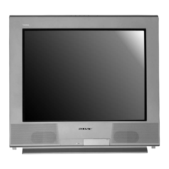
Sony TRINITRON KV-27FS13 Service Manual
Hide thumbs
Also See for TRINITRON KV-27FS13:
- Service manual (301 pages) ,
- Operating instructions manual (64 pages) ,
- Operating instructions manual (61 pages)
Advertisement
Quick Links
SERVICE MANUAL
MODEL NAME
KV-27FS13
KV-27FS13
KV-27FS17
KV-27FV17
KV-27FV17
KV-29FV17
KV-29FV17C
KV-32FS13
KV-32FS13
KV-32FS17
KV-34FS13C
KV-34FS17
KV-27FV17
9-965-911-01
REMOTE COMMANDER
DESTINATION
RM-Y180
RM-Y180
RM-Y181
RM-Y181
RM-Y181
RM-Y181
RM-Y181
RM-Y180
RM-Y180
RM-Y181
RM-Y180
RM-Y181
TRINITRON
BA-5
CHASSIS NO.
USA
SCC-S40NA
CND
SCC-S41LA
USA
SCC-S40PA
USA
SCC-S40MA
CND
SCC-S41KA
E
SCC-S38XA
E
SCC-S38YA
USA
SCC-S40QA
CND
SCC-S41MA
USA
SCC-S40RA
E
SCC-S56DA
E
SCC-S56JA
KV-27FS17
®
COLOR TELEVISION
Self Diagnosis
Supported model
CHASSIS
RM-Y181
Advertisement

Summary of Contents for Sony TRINITRON KV-27FS13
- Page 1 Self Diagnosis Supported model BA-5 SERVICE MANUAL CHASSIS MODEL NAME REMOTE COMMANDER DESTINATION CHASSIS NO. KV-27FS13 RM-Y180 SCC-S40NA KV-27FS13 RM-Y180 SCC-S41LA KV-27FS17 RM-Y181 SCC-S40PA KV-27FV17 RM-Y181 SCC-S40MA KV-27FV17 RM-Y181 SCC-S41KA KV-29FV17 RM-Y181 SCC-S38XA KV-29FV17C RM-Y181 SCC-S38YA KV-32FS13 RM-Y180 SCC-S40QA KV-32FS13 RM-Y180 SCC-S41MA KV-32FS17...
- Page 2 KV-27FS13/ 27FS17/ 27FV17/ 29FV17/ 29FV17C/ 32FS13/ 32FS17/ 34FS13C/ 34FS17 TABLE OF CONTENTS SECTION TITLE PAGE Specifi cations............................3 Warnings and Cautions........................4 Safety Check-Out..........................5 Self-Diagnostic Function........................6 1. Disassembly 1-1. Rear Cover Removal........................8 1-2. Chassis Assembly Removal......................8 1-3. Service Position ..........................8 1-4. Picture Tube Removal ........................9 Anode Cap Removal Procedure....................9 2.
- Page 3 The ( ) SRS (SOUND RETRIEVAL SYSTEM) is manufactured by YC-15V/30V, RK74A Sony Corporation under license from SRS Labs, Inc. It is covered by U.S. U/V mixer EAC-66 Patent No. 4,748,669. Other U.S. and foreign patents pending. TV Stand: SU-27FD4 (KV-27FS13/ 27FS17/ 27FV17 ONLY) TV Stand: SU-27FD3 (KV-29FV17/ 29FV17C ONLY) •...
- Page 4 Ne les remplacer que par des composants Sony dont le numero de piece est indique dans le present manuel ou dans des supplements publies par Sony. Les reglages de circuit dont l’importance est critique pour la securite du fonctionnement sont identifi...
- Page 5 KV-27FS13/ 27FS17/ 27FV17/ 29FV17/ 29FV17C/ 32FS13/ 32FS17/ 34FS13C/ 34FS17 SAFETY CHECK-OUT Leakage Test After correcting the original service problem, perform the following The AC leakage from any exposed metal part to earth ground and from safety checks before releasing the set to the customer: all exposed metal parts to any exposed metal part having a return to chassis, must not exceed 0.5 mA (500 microamperes).
- Page 6 KV-27FS13/ 27FS17/ 27FV17/ 29FV17/ 29FV17C/ 32FS13/ 32FS17/ 34FS13C/ 34FS17 Self Diagnosis SELF-DIAGNOSTIC FUNCTION Supported model The units in this manual contain a self-diagnostic function. If an error occurs, the STANDBY/TIMER LED will automatically begin to fl ash. The number of times the LED fl ashes translates to a probable source of the problem. A defi nition of the STANDBY/TIMER LED fl ash indicators is listed in the instruction manual for the user’s knowledge and reference.
- Page 7 KV-27FS13/ 27FS17/ 27FV17/ 29FV17/ 29FV17C/ 32FS13/ 32FS17/ 34FS13C/ 34FS17 Self-Diagnostic Screen Display For errors with symptoms such as “power sometimes shuts off” or “screen sometimes goes out” that cannot be confi rmed, it is possible to bring up past occurrences of failure on the screen for confi rmation. To Bring Up Screen Test In standby mode, press buttons on the Remote Commander sequentially, in rapid succession, as shown below: Display...


Need help?
Do you have a question about the TRINITRON KV-27FS13 and is the answer not in the manual?
Questions and answers