
Summary of Contents for HME Clear-Com Eclipse 12.1 HX-Omega
- Page 1 User Guide Eclipse 12.1 HX-Omega ® User Guide Part Number: PUB-00045 Rev A Date: January 22, 2021...
- Page 2 The product described in this document is distributed under licenses restricting its use, copying, distribution, and decompilation / reverse engineering. No part of this document may be reproduced in any form by any means without prior written authorization of Clear-Com, an HME Company.
-
Page 3: Table Of Contents
Eclipse HX-Omega | User Guide Table of contents 1 Important Safety Instructions 2 Introduction 2.1 Further Information 3 Overview 3.1 Eclipse HX Matrices 3.2 Eclipse HX-Omega Matrix 3.3 CPU Card 3.4 Interface Cards 3.5 Interface Modules 3.6 EHX Configuration Software 3.7 User Panels 4 Installing the Eclipse HX-Omega 4.1 Cabling Recommendations... - Page 4 Eclipse HX-Omega | User Guide 6.1 E-MADI64 Front Panel Lights and Controls 6.2 E-MADI64 Rear Panel Connectors 6.3 MADI Channels 6.4 Setting up the E-MADI64 Card 6.5 V-Series Panels on E-MADI (Multi-channel Audio Digital Interface) 6.6 Configuring Binaural Audio with E-MADI Cards 6.7 Configuring Binaural Panel Audio in Software 6.8 Set the EHX Audio Mixer Screen Option for Binaural Audio Routing 6.9 Upgrading the E-MADI64 Card...
- Page 5 Eclipse HX-Omega | User Guide 11.3 E-DANTE64-HX Front Panel Lights and Controls 11.4 E-DANTE64-HX Rear Panel Lights and Controls 11.5 Network Configuration 11.6 Installing a replacement or backup card 11.7 Upgrading your E-DANTE64-HX Card 11.8 Troubleshooting: Sample Rate 11.9 Troubleshooting: I Need to Find the E-DANTE64-HX Card’s IP Address 12 E-IPA-HX High Capacity IP to Matrix Card 12.1 Licenses 12.2 E-IPA-HX Rear Connectors...
- Page 6 Eclipse HX-Omega | User Guide 15.13 Fiber Transceiver 15.14 E-Que Interface Front Card 15.15 E-Que Interface Rear Card 15.16 IVC-32 Interface Front Card 15.17 IVC-32 Interface Rear Card 15.18 LMC-64 Interface Front Card 15.19 LMC-64 Interface Rear Card 15.20 E-DANTE64-HX Interface Front Card 15.21 E-DANTE64-HX Interface Rear Card 15.22 E-DANTE64-HX SFP Modules 15.23 E-DANTE64-HX LAN Connectors...
-
Page 7: Important Safety Instructions
Eclipse HX-Omega | User Guide Important Safety Instructions 1. Read these instructions. 2. Keep these instructions. 3. Heed all warnings. 4. Follow all instructions. 5. Do not use this apparatus near water. 6. Clean only with dry cloth. 7. Do not block any ventilation openings. Install in accordance with the manufacturer’s instructions. - Page 8 Eclipse HX-Omega | User Guide EMC AND SAFETY This Product's power supply meets all relevant CE, FCC, UL, and CSA specifications set out below: EN55103-1 Electromagnetic compatibility. Product family standard for audio, video, audio-visual, and entertainment lighting control apparatus for professional use. Part 1: Emissions.
-
Page 9: Introduction
Eclipse HX-Omega | User Guide Introduction The Eclipse HX system is a digital point-to-point intercom platform, designed to seamlessly integrate your entire your entire intercom infrastructure (digital, wireless, IP-based and analog intercom systems). The system comprises matrices, interface cards and modules, user panels and interface matrices. -
Page 10: Overview
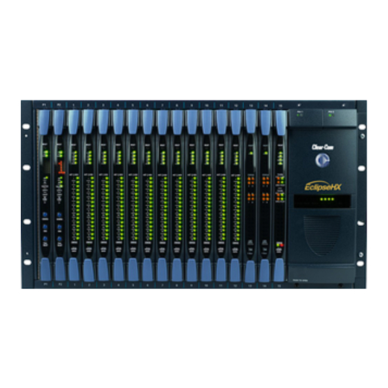
Eclipse HX-Omega | User Guide Overview This section provides an overview of the Eclipse HX-Omega matrix, including the extension cards and interface modules that can be fitted to the matrix. Eclipse HX Matrices There are four types of Eclipse HX system matrix available from Clear-Com: Matrix Description Eclipse HX-Omega... - Page 11 Eclipse HX-Omega | User Guide connected user panels, interface modules and other intercom devices. The central matrix itself consists of the matrix hardware (the Eclipse HX-Omega matrix) and the EHX configuration software. 3.2.1 Chassis and Assembly The matrix chassis is a metal rectangular box which measures six rack units (6RU) high and 19- inches wide (26.9 cm x 48.3 cm).
-
Page 12: Cpu Card
Eclipse HX-Omega | User Guide Support for multiple analog port interfaces (MVX-A16), providing 16 analog ports each. If MVX-A16 cards are fitted to all 15 slots available, the Eclipse HX-Omega can provide up to 240 analog ports. Fail-safe redundancy achieved by two processor cards and two power supplies. Note: Power supplies automatically switch to the correct voltage, for compatibility around the world. -
Page 13: Interface Cards
Eclipse HX-Omega | User Guide Stores up to four complete configurations, enabling the selection and activation of a configuration directly from the card. Includes an additional, embedded configuration, which may be activated from the card for fast fault checking after the installation or upgrade of the Eclipse HX system. Note A configuration determines the operating parameters of the Eclipse HX matrix system, including port functions, talk-and-listen audio routes, controls and other functions. - Page 14 Eclipse HX-Omega | User Guide You can only have four wireless E-Que cards You can only have four E-Que cards with EM signaling enabled. For the order in which all interface cards must be installed to the Eclipse HX-Omega, see Installing Interface Cards.
- Page 15 Eclipse HX-Omega | User Guide Each IVC-32 front card has status LEDs for power, port activity and LAN status. The LAN indicators show whether there is a LAN connection and the IP activity on the LAN port. A total of four E-Que, IVC-32 or LMC-64 interface cards may be fitted to an Eclipse HX-Omega unless the matrix is fitted with a Power-One/Bel Fuse PSU.
- Page 16 Eclipse HX-Omega | User Guide A total of four E-Que, IVC-32 or LMC-64 interface cards may be fitted to an Eclipse HX-Omega unless the matrix is fitted with a Power-One/Bel Fuse PSU. If the matrix has a Power-One/Bel Fuse PSU, up to six E-Que, IVC-32 or LMC-64 cards may be fitted with the following condition: You can only have four wireless E-Que cards You can only have four E-Que cards with EM signaling enabled.
-
Page 17: Interface Modules
Eclipse HX-Omega | User Guide Interface Modules Interface modules convert the 4-wire signals of a central matrix port to other types of signals that communicate with devices such as telephones, camera intercoms, two-way radios, and so on. In this way non-4-wire devices can communicate with the central matrix. Note: The term central matrix is used to differentiate the core hardware and software from the connected intercom panels and interfaces. -
Page 18: Ehx Configuration Software
Eclipse HX-Omega | User Guide AES-6 DIG-2 EHX Configuration Software The EHX configuration software controls the operation of the connected audio devices by sending signals to the circuit cards in the matrix, which then relays the signals to the audio devices. Configurations (the operating parameters of complete system setups) are created and managed in EHX. -
Page 19: User Panels
Eclipse HX-Omega | User Guide The EHX system can be set up to run on a client/server model over a network, allowing the system administrator to control the matrix remotely. User Panels All intercom panels connect to the central matrix using shielded CAT5 cable terminated with RJ-45 connectors. -
Page 20: Installing The Eclipse Hx-Omega
Eclipse HX-Omega | User Guide Installing the Eclipse HX-Omega This section describes how to install the Eclipse HX-Omega matrix, including the power supplies, connector panels, CPU cards, the port and expansion cards. It also describes how to connect interface cards, interface modules and intercom (user) panels to the matrix. - Page 21 Eclipse HX-Omega | User Guide Check the packing list and verify that every item on the list has been received. Save all packing materials in the event that any items need to be returned. 4.2.2 Unpacking the System When the Eclipse HX-Omega system is received the circuit cards, power supplies, and rear- connector panels are pre-installed in the matrix chassis.
- Page 22 Eclipse HX-Omega | User Guide Eclipse HX-Omega CPU cards are fitted with a socketed battery which is normally a Renata CR2477N with a capacity of 950mAh and a life of approximately 247 days. These socketed batteries are easily replaced and this operation does not have to be carried out by service personnel.
-
Page 23: Installing The Eclipse Hx-Omega
Eclipse HX-Omega | User Guide If this state is detected by the CPU card then the CPU card will provide signalization on its OK LED in the form of 2 rapid flashes followed by a slow flash of the OK LED. If EHX is logging, then the following message will appear in the log: Non Volatile Data is invalid - Please check Battery Voltage If on successive power downs of the HX-Omega matrix the above state is detected, and the... - Page 24 Eclipse HX-Omega | User Guide Two identical Euro Cassette power supplies are provided to ensure that every matrix will have redundant power (ensuring that the matrix will continue to operate even if one supply output fails). Each of the power supplies must be connected to a dedicated branch of AC mains power. The matrix will continue to operate even if one of the AC power branches fails.
-
Page 25: Installing Cpu Cards
Eclipse HX-Omega | User Guide Installing CPU Cards The CPU card’s components include CMOS chips which are sensitive to static electricity. Before touching the CPU card touch a grounded metal object, such as any unpainted surface on the matrix, to dissipate static electricity. While handling the CPU card, take care not to bend any of the card’s connector pins or component leads. - Page 26 Eclipse HX-Omega | User Guide 1. Hold the card in place in the matrix. 2. There are two card ejector tabs, located at the top and bottom of the CPU card. Open the two ejector tabs at the same time until the card unseats from its backplane connectors. 3.
- Page 27 Eclipse HX-Omega | User Guide Page 27...
-
Page 28: Installing Interface Cards
Eclipse HX-Omega | User Guide Note: Once the CPU card has initialized, you can use the Eng button (press and release) to request matrix information (such as the software version and the current IP address. For more detailed information about the CPU card lights and controls, see CPU Card Lights and Controls. - Page 29 Eclipse HX-Omega | User Guide More ports can be utilized on the Eclipse HX-Omega by using higher capacity interface cards, such as the E-MADI64 card. (5 E-MADI64 cards * 64 ports) + (10 MVX-A16 cards * 16 ports) = 480 Note: A total of four E-Que, IVC-32 or LMC-64 interface cards may be fitted to an Eclipse HX- Omega unless the matrix is fitted with a Power-One/Bel Fuse PSU.
- Page 30 Eclipse HX-Omega | User Guide An interface card’s components include CMOS chips that are sensitive to static electricity. Before touching a card first touch a grounded metal object, such as any unpainted surface on the matrix, to dissipate static electricity. When handling a card, be careful not to bend any of the card’s connector pins or component leads.
- Page 31 Eclipse HX-Omega | User Guide Page 31...
-
Page 32: Wiring Audio Devices To The Matrix
Eclipse HX-Omega | User Guide Note: For more detailed information about the MVX-A16 front panel controls and lights, see Analog Port Card (MVX-A16) Front-Panel Lights and Controls 4.5.6 Slot Numbering Each MVX-A16 interface card has circuitry to support 16 analog ports. A grid printed on the matrix’s rear panel gives the numbering scheme for the analog ports. -
Page 33: Wiring Panels To The Matrix
Eclipse HX-Omega | User Guide Wiring Panels to the Matrix Eclipse HX uses a 4-pair (analog) or single-pair (digital) wiring scheme between the matrix and panels. All Eclipse HX panels have built-in RJ-45 connectors. 4.7.1 4-Pair Analog Four-pair analog wiring is performed with shielded CAT5 RJ-45 cable: Pair Description Pair 1... - Page 34 Eclipse HX-Omega | User Guide 4.7.2 Single-Pair Digital Single-pair digital wiring is accomplished with double-shielded 24 AWG conductor CAT-6E enhanced STP cable. Pair 1 transmits and receives multiplexed digital and analog between the matrix and the panel. Ensure that the Select switch on the rear of the panel is in the correct position for the intended use.
-
Page 35: Wiring Cpu Card Interfaces
Eclipse HX-Omega | User Guide Note: The above wiring diagram refers to DIG-2 only Wiring CPU Card Interfaces The CPU card holds the circuitry for connecting to, and communicating with, the following interfaces: An external personal computer. Alarm inputs and outputs. Eight general purpose inputs (GPIs). - Page 36 Eclipse HX-Omega | User Guide 4.8.1 CPU Card Interface Connectors Page 36...
- Page 37 Eclipse HX-Omega | User Guide CPU card interface connectors Feature Description GPI/RLY Interface Connector The RJ-45 socket labeled GPI/RLY Interface connects the CPU card to a GPI-6 or RLY-6 card. The GPI-6 provides six general-purpose opto-isolated logic inputs. The RLY-6 card provides six single-pole, double-throw relay outputs.
- Page 38 Eclipse HX-Omega | User Guide CPU card interface connectors PC DB-25F connector to matrix DB-9M... Page 38...
- Page 39 Eclipse HX-Omega | User Guide CPU card interface connectors Page 39...
- Page 40 Eclipse HX-Omega | User Guide CPU card interface connectors Alarm I/O Connector The DB-9F connector labeled Alarm I/O connects the matrix to a control circuit for an external alarm, such as a light or bell. The external alarm activates whenever an alarm condition is detected in the matrix. The following conditions trigger an alarm: If any of the voltages produced by the first power supply unit fall below their normal levels.
- Page 41 Eclipse HX-Omega | User Guide CPU card interface connectors Wiring the Alarm I/O DB-9F to the Alarm Relay connector Page 41...
- Page 42 Eclipse HX-Omega | User Guide CPU card interface connectors Double-pole double-throw alarm relay General-Purpose Outputs Connector (GP OUT) A GPO can be programmed to mute a speaker, to turn on an applause light, to turn on a door lock, or to perform a variety of other functions. For example, to get the attention of a panel operator working in a high-noise environment such as a control booth, a relay can be programmed to switch on a light at the operator panel each time an incoming call is received, to ensure that the call is...
- Page 43 Eclipse HX-Omega | User Guide CPU card interface connectors General-Purpose Inputs Connector (GP IN) The DB-25 connector labeled GP IN connects the matrix to eight local general- purpose inputs (GPIs). An external device such as a foot switch, a panel-mounted switch or the logic output of some other device can be connected to the GP IN connector. ...
- Page 44 Eclipse HX-Omega | User Guide CPU card interface connectors The opto-isolated mode requires the externally connected equipment to provide the current to power the general-purpose input. The non-isolated mode does not require that the externally connected equipment powers the general- purpose input.
- Page 45 Eclipse HX-Omega | User Guide CPU card interface connectors active input. The voltage level at the external input pin should not be allowed to go below ground or above +6 V with respect to ground. Pin configuration of the General Inputs connector Page 45...
- Page 46 Eclipse HX-Omega | User Guide CPU card interface connectors Local Area Network connector (LAN1) The LAN1 and LAN2 connectors have standard Ethernet pin assignments. See G below for pin assignments. The RJ-45 socket labeled LAN 1 connects a local area network (LAN) to the CPU card through a standard Ethernet connection.
-
Page 47: Dse1/T1 Matrix To Matrix Crossover Cable Connections
Eclipse HX-Omega | User Guide CPU card interface connectors Note:If this port is used a ferrite core must be added to the socket end of each cable. A suitable ferrite core is Würth Electronik part: 74271132. A shielded CAT5 cable should be used. DSE1/T1 Matrix to Matrix Crossover Cable Connections For E1 and T1 direct matrix to matrix connections the CAT5 crossover cables should be wired. -
Page 48: E1 To Freespeak Ii™ Antenna Straight Cable Connection
Eclipse HX-Omega | User Guide Matrix 1 Pin Description Matrix 2 Pin Not connected 4.11 E1 to FreeSpeak II™ Antenna Straight Cable Connection Straight CAT-5 cables are used to connect an E-Que card to a FreeSpeak II antenna or splitter. The E1 pinout for connecting an antenna or splitter is shown in the following table. -
Page 49: Using The Eclipse Hx-Omega
Eclipse HX-Omega | User Guide Using the Eclipse HX-Omega This section describes how to use (operate) the Eclipse HX-Omega matrix and its circuit cards. The Eclipse HX-Omega matrix chassis houses the circuit cards, power supplies, and connectors that form the central hardware of the system. Various types of Eclipse HX-Omega circuit cards perform unique functions: CPU cards control overall system operation. -
Page 50: Setting The Default Ip Address
Eclipse HX-Omega | User Guide Setting the Default IP Address To reset the CPU LAN ports to their default IP addresses, press and hold the ENG and FULL RESET buttons on the CPU front card until the card resets. Note: Do not release the ENG and FULL RESET buttons until the CPU card LED panel shows either an A or a B. -
Page 51: Cpu Card Fail-Safes
Eclipse HX-Omega | User Guide If the network mask is extended to 255.255.255.0 the network ID becomes 172.16.2 so the second port could have an address of 172.16.3.1 and a mask of 255.255.255.0 giving a network ID of 172.16.3 for the second port. If both Ethernet ports are set up with the same network ID this condition results in data loss on one or both of the Ethernet ports. -
Page 52: Cpu Card Lights And Controls
Eclipse HX-Omega | User Guide CPU Card Lights and Controls Page 52... - Page 53 Eclipse HX-Omega | User Guide CPU card lights and controls Feature Description RESET button Pressing the RESET button causes the CPU card to stop its current activity and to restart. The same configuration that was active before the system was reset will be active after the system was reset.
- Page 54 Eclipse HX-Omega | User Guide CPU card lights and controls When an older, unsupported version of the MVX or E-Que FPGA is detected, the EQue FPGA VERSION UNSUPPORTED message is displayed by the master CPU card. Note: The dot matrix lights will also display system information when the ENG button is pressed on the master CPU card.
- Page 55 Eclipse HX-Omega | User Guide CPU card lights and controls SI Light The SI light flashes to indicate communications activity. Configuration [ CONFIG ] button The CPU card can hold four complete system configurations in its operational memory. When the CONFIG button is pressed the number of the currently active configuration (either 1, 2, 3, or 4) appears in the dot-matrix display.
- Page 56 Eclipse HX-Omega | User Guide CPU card lights and controls Eclipse IP address. IP address of the LAN 1 port, for example 169.254.000.100. Note: If this address was not statically allocated, but instead was allocated via DHCP server this will be pre-pended by DHCP ENABLED. System number.
- Page 57 Eclipse HX-Omega | User Guide 5.5.1 Using the Embedded Configuration In addition to the four EHX configurations that can be stored on the card, the CPU card also includes an embedded configuration. The embedded configuration is designed for fast fault checking following a system upgrade or field install (for example, checking hardware connections with user panels and interface cards).
-
Page 58: Analog Port Card (Mvx-A16) Front-Panel Lights And Controls
Eclipse HX-Omega | User Guide Analog Port Card (MVX-A16) Front-Panel Lights and Controls Analog port card (MVX-A16) lights and controls Feature Description Page 58... - Page 59 Eclipse HX-Omega | User Guide Analog port card (MVX-A16) lights and controls RESET button Pressing the RESET button causes the card and all connected audio devices to momentarily stop their current activity and to restart. The card’s “matrix data” light goes off when the reset starts and comes back on when the reset is complete.
-
Page 60: Power Supplies
Eclipse HX-Omega | User Guide Analog port card (MVX-A16) lights and controls VOX Lights When lit a VOX light indicates that the audio level on a connected device, such as an intercom panel or interface, has exceeded a preset threshold. The threshold audio level is set through the EHX application. - Page 61 Eclipse HX-Omega | User Guide A fan tray is recommended if you are using more than four E-Que, IVC-32 or LMC-64 cards. The different types of power supply units must not be mixed in an Eclipse HX- Omega matrix; if one of the pair of power supplies is replaced it must be replaced with the same type of power supply unit.
-
Page 62: Diagnosing Power Supply Problems
Eclipse HX-Omega | User Guide Diagnosing Power Supply Problems The image above illustrates the front panel alarm lights, power supply lights, and reset button. An alarm source triggers the main alarm light and also one of the additional six red alarm lights, allowing the system operator to identify or correct alarm conditions before they affect the operation of the matrix. - Page 63 Eclipse HX-Omega | User Guide 720379Z) should not be adjusted. 5.8.1 Conditions that Cause an Alarm The following conditions trigger an alarm: If any of the voltages produced by the first power supply unit fall below normal levels. If any of the voltages produced by the second power supply unit fall below normal levels.
- Page 64 Eclipse HX-Omega | User Guide If a new alarm condition or conditions occur before the original alarm conditions are corrected, the internal buzzer and relay contacts will not reactivate. They will only reactivate after all original alarm conditions are corrected. 5.8.4 Auxiliary Alarm Lights When an alarm condition occurs, any of the six auxiliary alarm lights may switch on, in addition to...
-
Page 65: Connecting The Matrix
Eclipse HX-Omega | User Guide When the first power supply unit is operating correctly, the red PSU2 light stays off, while the four green power supply lights (+12V, +5V, +3.3V, -12V) stay on continuously. If a DC output or AC input to the first power supply drops too low, the red PSU2 light switches on. The amber (XP) or red (Power-One/Bel Fuse) light on the power supply unit itself also switches on to indicate the same condition. - Page 66 Eclipse HX-Omega | User Guide 5.9.1 Eclipse HX-Omega Rear Connector Panels There are seven types of rear-connector panels: Panel Description CPU card A CPU-card rear panel holds the various connectors associated with the CPU card, such as the RS-232 connector for the configuration computer. Analog port card (MVX-A16) Analog port-card rear panel holds the sixteen RJ-45 connectors associated with its corresponding analog...
- Page 67 Eclipse HX-Omega | User Guide Panel Description E-Que card An E-Que card provides eight RJ-45 ports for connection to wireless equipment and three RJ-45 ports for DECT sync and LAN connections. IVC-32 card An IVC-32 card provides a RJ-45 port for connection to an IP network.
- Page 68 Eclipse HX-Omega | User Guide A MADI fiber connector. MADI input and output coaxial cable connectors. A coaxial Video / Word clock input. Each rear connector panel associated with an E-Que interface card comprises eleven RJ-45 ports: Eight ports for connection to wireless equipment. Two ports for DECT sync.
-
Page 69: Madi64 Card
Eclipse HX-Omega | User Guide E-MADI64 Card This section describes the E-MADI64 card. The E-MADI64 is a MADI (Multichannel Audio Digital Interface) card, providing up to 64 duplex channels of AES3 digital audio over a coaxial cable or fiber pair between compatible devices. -
Page 70: E-Madi64 Front Panel Lights And Controls
Eclipse HX-Omega | User Guide E-MADI64 Front Panel Lights and Controls Page 70... - Page 71 Eclipse HX-Omega | User Guide On a card with a clock source and MADI connections (where the received MADI signal matches the card set up), the following lights are lit: Lock source LED [C], the Sample rate (Fs) LED [ D ], the Channels LED [ E ] and the Active LED [ F ].
- Page 72 Eclipse HX-Omega | User Guide Key to E-MADI64 front panel lights and controls Channels A green LED indicates the quantity of MADI channels. The number of channels is determined in EHX. You can select from 32, 56 or 64 full duplex channels of digital audio.
-
Page 73: E-Madi64 Rear Panel Connectors
Eclipse HX-Omega | User Guide E-MADI64 Rear Panel Connectors Warning: Eye Safety This LED based single mode transceiver is a Class 1 LED product. It complies with IEC 60825-1/A2:2001 and FDA performance standards for laser products (21 CFR 1040.10 and 1040.11) except for deviations pursuant to Laser Notice 50, dated July 26, 2001. -
Page 74: Madi Channels
Eclipse HX-Omega | User Guide Key to E-MADI64 rear panel connectors MADI IN coaxial connector MADI OUT coaxial connector Video / Word clock coaxial connector The clock source is either NTSC/PAL Black and burst, Tri Level HD video sync or AES Word Clock. MADI Channels The E-MADI64 card can route up to 64 MADI channels of audio. -
Page 75: Setting Up The E-Madi64 Card
Eclipse HX-Omega | User Guide To disable the ID and use the EHX port name. Setting up the E-MADI64 Card To set up the E-MADI card: 1. With the Eclipse HX-Omega powered off, insert the E-MADI front and rear cards into the matrix. -
Page 76: V-Series Panels On E-Madi (Multi-Channel Audio Digital Interface)
Eclipse HX-Omega | User Guide 6.4.1 Connecting a Word Clock Source If you connect the Word Clock source to the Clock Input connector on the rear card (see the table in Setting up the E-MADI64 Card). The WRD LED on the front of the E-MADI64 card is lit solid green, indicating that the word clock has been detected and locked onto. - Page 77 Eclipse HX-Omega | User Guide Run EHX version 8.5 or above. Configure the panel audio in the EHX software and the MADI software as necessary. Ensure that the panel is fitted with a V-Series AES options module (see the V-Series Panel User Guide and the V-Series Main Panel Rear Connectors (AES 3) section for more information.) How the ports are configured in the software will depend on which MADI is used.
- Page 78 Eclipse HX-Omega | User Guide 6.5.2 Configuring Audio over Optocore/ProGrid MADIs Optocore/ProGrid MADIs have the advantage of allowing fully flexible audio routing. Optocore/ProGrid interfaces allow each channel of the MADI to be routed individually to any channel on any destination node. The AES streams do not have to be routed and configured in pairs.
-
Page 79: Configuring Binaural Audio With E-Madi Cards
Eclipse HX-Omega | User Guide Configuring Binaural Audio with E-MADI Cards When routing audio to a V-Series panel with a MADI64 card, the AES (Audio Engineering Society) audio streams can be set to operate binaurally (one channel to each headphone on a headset) using the main channel audio (A) and the auxiliary channel audio (B). - Page 80 Eclipse HX-Omega | User Guide 6.7.1 Binaural Audio over MADI, the General Case Most third party equipment (e.g. RME, Lawo) treats the AES streams from a MADI interface as 32 linked pairs, A and B channel together. So in the general case, the following strategy should be used to route the AES streams for binaural audio: In the card/port configuration screen in EHX, the panels should be defined on the odd numbered ports (taking the first port as 1) of the E-MADI card.
-
Page 81: Set The Ehx Audio Mixer Screen Option For Binaural Audio Routing
Eclipse HX-Omega | User Guide In all cases, when using a router such as ProGrid, ensure that the configuration of the E-MADI card and the configuration of the ProGrid matrix are consistent with each other. For example, if ports 1,2,3,4,5,7,9,11… are defined as panels in EHX, the ProGrid must be used to ensure that the channels 1,2,3,4,5,7,9,11…... -
Page 82: Fib Fiber Card
Eclipse HX-Omega | User Guide E-FIB Fiber Card This section describes how to connect Eclipse matrices using E-FIB fiber interfaces. E-FIB fiber interfaces connect Eclipse HX matrices together to provide a high speed, dual redundant link to transfer audio samples and data between systems. These connections can be configured in various ways to provide protection against the loss of a link or a node. -
Page 83: E-Fib Front Panel Lights And Controls
Eclipse HX-Omega | User Guide E-FIB Front Panel Lights and Controls Page 83... - Page 84 Eclipse HX-Omega | User Guide Key to E-FIB front panel lights and controls Feature Description RESET button Pressing the RESET button causes the card and all links to momentarily stop their current activity and to restart. The card’s matrix data light goes off when the reset starts and comes back on when the reset is complete.
- Page 85 Eclipse HX-Omega | User Guide Key to E-FIB front panel lights and controls When lit, this red LED indicates that an error condition has been detected on the primary fiber optic circuit. TXVR LED When lit, this green LED indicates when data is being transmitted on the primary circuit.
-
Page 86: E-Fib Rear Panel Lights And Connectors
Eclipse HX-Omega | User Guide E-FIB Rear Panel Lights and Connectors Page 86... - Page 87 Eclipse HX-Omega | User Guide Warning: Eye Safety This laser based single mode transceiver is a Class 1 Laser product. It complies with IEC 60825-1/A2:2001 and FDA performance standards for laser products (21 CFR 1040.10 and 1040.11) except for deviations pursuant to Laser Notice 50, dated July 26, 2001. Normally a protective plug is fitted to the fiber connector to protect the connector from damage or the entry of foreign materials.
-
Page 88: Configuring A Fiber Optic Connection
Eclipse HX-Omega | User Guide Configuring a Fiber Optic Connection There are a number of ways that optical connections can be made between systems depending on the level of redundancy required. When a break occurs in the fiber ring, a solid red status light will be shown at the fiber card downstream from the break and the link status LEDs may show amber. -
Page 89: Simplex Fiber Cabling
Eclipse HX-Omega | User Guide In order to diagnose faults or switch between primary and secondary rings or between primary and backup fiber linking cards the system monitoring screen in EHX must be used. Note For more information about EHX, see your EHX documentation (including EHX Help). Simplex Fiber Cabling 7.4.1 Single Card Set Redundancy... - Page 90 Eclipse HX-Omega | User Guide Loss of single fiber connection When there is no break in the fiber connections the fiber audio will be routed using the primary ring. If there is any connection failure on the primary ring and the secondary ring is intact then the fiber audio routing will move to the secondary ring.
- Page 91 Eclipse HX-Omega | User Guide If two non-adjacent nodes are lost on the ring the nodes adjacent to the failures will loop-back their connections to the failed nodes healing the ring into 2 separate smaller rings. The configuration software (EHX) will report the failure. Note: In this instance the two sub-rings will be dependent on their Ethernet connections for configuration and data transmission but there will be no audio path between them.
- Page 92 Eclipse HX-Omega | User Guide Audio and data from a failed node will not be available to the remaining nodes for the duration of the failure. When a ring with non-adjacent failures sub-divides into two sub-rings, audio and data from the failed nodes will not be available to the nodes in either sub-ring. Audio and data will continue to be available to nodes within the same sub-ring but data may still be available to all nodes that are still functioning if there is an intact, independent Ethernet connection to those nodes.
- Page 93 Eclipse HX-Omega | User Guide Page 93...
-
Page 94: Que E1 / T1 Card
Eclipse HX-Omega | User Guide E-Que E1 / T1 Card The E-Que interface card allows you to connect the Eclipse HX-Omega to FreeSpeak II antennas and antenna splitters, E1 and T1 trunk lines and E1 direct lines. Each E-Que interface card comprises: A front card with a reset button and various status indicators (LEDs for power, port activity and LAN status). - Page 95 Eclipse HX-Omega | User Guide 30 audio channels on each of 2 connectors (60 channels in total) available in E1 mode. 24 audio channels on each of 2 connectors (48 channels per card in total) are available in T1 mode. Page 95...
-
Page 96: Que Front Panel Lights And Controls
Eclipse HX-Omega | User Guide Que Front Panel Lights and Controls Page 96... - Page 97 Eclipse HX-Omega | User Guide Key to E-Que front panel lights and controls Feature Description RESET button Pressing the reset button causes the card and all links to momentarily stop their current activity and to restart. During the reset, configuration information downloads to the card from the CPU card.
-
Page 98: E-Que Rear Panel Connectors
Eclipse HX-Omega | User Guide E-Que Rear Panel Connectors Page 98... -
Page 99: Synchronization
Eclipse HX-Omega | User Guide Key to E-Que rear panel connectors Feature Description LAN port (RJ-45) The LAN port is used for diagnostic purposes. DECT sync ports: DECT Ref in DECT Ref out E1 / T1 Port 1 (RJ-45) E1 / T1 Port 2 (RJ-45) E1 / T1 Port 3 (RJ-45) E1 / T1 Port 4 (RJ-45) E1 / T1 Port 5 (RJ-45) -
Page 100: E-Que Interface Application
Eclipse HX-Omega | User Guide E-Que Interface Application The E-Que interface may be used to connect: FreeSpeak II antennas and splitters to an Eclipse HX-Omega matrix. Provide E1 and T1 connections to other systems. Note: For more information about E1 and T1 cable pinouts and cable connections, see: E1/T1 Matrix to Matrix straight cable connections. - Page 101 Eclipse HX-Omega | User Guide Page 101...
- Page 102 Eclipse HX-Omega | User Guide Each antenna can handle up to five beltpacks simultaneously and switch service between antennas under control of the matrix as the beltpack user moves around the site. 8.6.2 Recommended Powering and Cable Lengths The tables in this section list the maximum cable distances and power requirements for a FreeSpeak II matrix system.
- Page 103 Eclipse HX-Omega | User Guide 24 AWG Cat5/6 shielded cable Splitter to transceiver (no local transceiver power) 100 m (328 feet) Splitter to transceiver (with local transceiver power) 800 m (2624 feet) 26 AWG Cat5/6 shielded cable System components Distance Matrix to transceiver (with local transceiver power) 400 m (1312 feet) Matrix to splitter...
- Page 104 Eclipse HX-Omega | User Guide Notes All connections are made using CAT-5 cable and it is recommended that shielded cable is used. If an E-Que interface is fitted in the matrix with antennae or splitters connected and active Page 104...
-
Page 105: E1 Trunk And Direct Modes
Eclipse HX-Omega | User Guide inserting a second E-Que interface to the left of the first interface (seen from the front) will cause a temporary loss of audio to beltpacks using the original E-Que interface (usually for about 10 seconds). The beltpacks do not go offline and signalization is not lost. E1 Trunk and Direct Modes The E-Que interface card can be used for both direct E1 to E1 port connections or to provide trunk linking via a network between systems. ... - Page 106 Eclipse HX-Omega | User Guide E1 trunking between matrices can also be achieved over an E1 network, as shown in the diagram below. In this case E1 ports 1 and 5 of the E-Que interface are connected using standard straight-through CAT-5 cables rather than crossover CAT-5 cables.
- Page 107 Eclipse HX-Omega | User Guide The E-Que interface can also be used to connect the matrix to third party equipment using E1 port 1 or 5. Page 107...
-
Page 108: T1 Trunking
Eclipse HX-Omega | User Guide The CAT-5 cable connecting the E1 port on the E-Que rear card may be a crossover cable or a straight-through cable depending on the requirements of the third party equipment. The E-Que interface should be set to Direct in EHX. T1 Trunking The E-Que interface card can provide T1 trunking between Eclipse HX systems and between Eclipse HX systems and compatible third-party equipment. - Page 109 Eclipse HX-Omega | User Guide Balanced. 120 Ohm Line Impedance. No Signaling. G.722 64 kbit/s Audio Encoding. Tx Clock locally generated. Rx Clock Line Recovered. T1 trunking between matrices can also be achieved over an E1 network as shown in the following diagram.
-
Page 110: Trunking Failover
Eclipse HX-Omega | User Guide Trunking Failover Where the E1/T1 trunking has been configured with redundant trunks, audio will be switched from the primary trunk to the backup trunk when a failure is detected. When failover occurs from primary to backup there will be a three second audio break on any route running over the trunk. -
Page 111: Ivc-32 Card For Ip-Based Connections
Eclipse HX-Omega | User Guide IVC-32 Card for IP-Based Connections The IVC-32 (Instant Voice Communication) interface card provides the Eclipse HX-Omega with connectivity over IP to V-Series IP panels and Concert servers. Each IVC-32 interface card comprises: A front card with a reset button and various status indicators (including status LEDs for power, port activity and LAN status). -
Page 112: Ivc-32 Front Panel Lights And Controls
Eclipse HX-Omega | User Guide IVC-32 Front Panel Lights and Controls Page 112... - Page 113 Eclipse HX-Omega | User Guide Key to IVC-32 front panel lights and controls Feature Description RESET button Pressing the reset button causes the card and all links to momentarily stop their current activity and to restart. During the reset, configuration information downloads to the card from the CPU card.
-
Page 114: Ivc-32 Rear Panel Connectors
Eclipse HX-Omega | User Guide IVC-32 Rear Panel Connectors Page 114... -
Page 115: Ivc-32 Interface Card Applications
Eclipse HX-Omega | User Guide Key to IVC-32 rear panel connectors Feature Description LAN port (RJ-45) DECT sync ports: DECT Ref in (Not used) DECT Ref out (Not used) E1 / T1 Port 1 (Not used) E1 / T1 Port 2 (Not used) E1 / T1 Port 3 (Not used) E1 / T1 Port 4 (Not used) E1 / T1 Port 5 (Not used) - Page 116 Eclipse HX-Omega | User Guide The advantage of using IP communication is that it enables remote panels to communicate over an existing local (LAN) or wide area (WAN) network rather than requiring a dedicated link. 9.3.2 IP Linking and Trunking The Eclipse IVC-32 cards allow directs and trunks over IP network infrastructure.
-
Page 117: Lmc-64 Metering Card
Eclipse HX-Omega | User Guide LMC-64 Metering Card The Level Meter Card (LMC-64) interface enables the Eclipse HX-Omega to provide audio level metering for Dynam-EC over a network. Each LMC-64 interface card can meter up to 64 partylines and four-wire ports. The LMC-64 card set comprises: A front card with a reset button and various status indicators (including status LEDs for power, port activity and LAN status). -
Page 118: Lmc-64 Front Panel Lights And Controls
Eclipse HX-Omega | User Guide 10.1 LMC-64 Front Panel Lights and Controls Page 118... - Page 119 Eclipse HX-Omega | User Guide Key to IVC-32 front panel lights and controls Feature Description RESET button Pressing the reset button causes the card and all links to momentarily stop their current activity and to restart. During the reset, configuration information downloads to the card from the CPU card.
-
Page 120: Lmc-64 Rear Panel Connectors
Eclipse HX-Omega | User Guide 10.2 LMC-64 Rear Panel Connectors Page 120... -
Page 121: Lmc-64 Interface Card Applications
Eclipse HX-Omega | User Guide Key to LMC-64 rear panel connectors Feature Description LAN port (RJ-45) DECT sync ports: DECT Ref in (Not used) DECT Ref out (Not used) E1 / T1 Port 1 (Not used) E1 / T1 Port 2 (Not used) E1 / T1 Port 3 (Not used) E1 / T1 Port 4 (Not used) E1 / T1 Port 5 (Not used) - Page 122 Eclipse HX-Omega | User Guide Page 122...
-
Page 123: Dante64-Hx Card
Eclipse HX-Omega | User Guide E-DANTE64-HX card E-DANTE64-HX card includes licence from Audinate Pty Ltd under U.S. patent number(s) 7747725, 8005939, 7978696, 8171152 and other patents issued, see www.audinate.com/patents This section contains information about audio networking using an E-DANTE64-HX interface card. -
Page 124: Example Applications
Eclipse HX-Omega | User Guide 11.1 Example Applications 11.1.1 Interruptible Foldback (IFB) over Dante Page 124... -
Page 125: Using The E-Dante64-Hx Card
Eclipse HX-Omega | User Guide 11.1.2 Live Performance Interface with Digital Intercom 11.2 Using the E-DANTE64-HX Card To route audio using an E-DANTE64-HX card you must already have the Audinate Dante Controller installed on your PC (or similar device that can set up Dante routes). The Dante Controller can be downloaded from the Audinate website. - Page 126 Eclipse HX-Omega | User Guide 3. Connect the secondary network to the secondary network switch on the E-DANTE64-HX card (if you are using a secondary network). Note: The card can be used with an RJ45 Ethernet or a Fiber Ethernet connection for either network.
-
Page 127: E-Dante64-Hx Front Panel Lights And Controls
Eclipse HX-Omega | User Guide 11.3 E-DANTE64-HX Front Panel Lights and Controls Page 127... - Page 128 Eclipse HX-Omega | User Guide Feature Description Reset button Pressing the Reset button causes the card and all links to momentarily stop their current activity and to restart. The flashing green Active light goes off when the reset starts and comes back on when the reset is complete.
- Page 129 Eclipse HX-Omega | User Guide Feature Description Fiber connection is always 1Gbps and is always green. Active LED The Active (matrix data) LED flashes green (1:1 at 1Hz) to indicate successful communication between the E-DANTE64-HX interface and the CPU card. This LED will flash twice as fast while a card is being upgraded and firmware is being installed (EHX firmware only, the light will stay as normal while Dante firmware is being installed).
-
Page 130: E-Dante64-Hx Rear Panel Lights And Controls
Eclipse HX-Omega | User Guide 11.4 E-DANTE64-HX Rear Panel Lights and Controls Page 130... -
Page 131: Network Configuration
Eclipse HX-Omega | User Guide Feature Description Primary network connector RJ45 See Note below. Primary network connector Fiber You will install a Clear-Com SFP/Mini-GBIC in this slot. See Specifications section for details. Primary Fiber connection LEDs The green LED indicates that the network (Primary or Secondary) is successfully connected. -
Page 132: Installing A Replacement Or Backup Card
Eclipse HX-Omega | User Guide A Dante-enabled device connected to a network will automatically setup its own network configuration, including its IP address. If the network has a DHCP server, which may be the case for installed networks, it will receive its IP configuration using the standard DHCP protocol. - Page 133 Eclipse HX-Omega | User Guide The upgrade process for each of the two modules on the card (EHX and Dante) is different. The two processes are outlined below. Note When upgrading your E-DANTE64-HX card, only use the Clear-Com supplied upgrade files for both: (A: EHX) ClearCom - App, Boot, DSP, FPGA: ...
- Page 134 Eclipse HX-Omega | User Guide While the E-DANTE64-HX card is being upgraded with EHX firmware, the active light (green) on the front of the device will flash at double its usual speed and the error light (red) will show. The card is ready for use when the error light is off and the status light has returned to a steady 1Hz pulse.
-
Page 135: Troubleshooting: Sample Rate
Eclipse HX-Omega | User Guide 11.8 Troubleshooting: Sample Rate Dante devices must be set to the same sample rate for audio to pass between them. Set sample rate for all devices in the Dante Controller. right-click on device icon in the Routing page to open Device View>Device Config. - Page 136 Eclipse HX-Omega | User Guide 11.9.2 Make Sure both Devices Are on the Same Subnet In order to be able to configure the E-DANTE64-HX card as usual, you must make sure that the PC hosting the controller is in the same IP range (subnet) as the card. Once you have reset the IP address of the PC accordingly, the ‘misplaced’...
- Page 137 Eclipse HX-Omega | User Guide 11.9.4 Link-Local The link-local IP range is a special case (169.254.1.0 – 169.254.254.255). The Dante Controller will NOT see an E-DANTE64-HX card with a link-local IP address if the PC hosting it is not set to the link-local IP range also. In this case, you need to change the PC’s IP address to a value in the link-local range before you can access and configure the card.
- Page 138 Eclipse HX-Omega | User Guide AES67 uses IEEE1588-2008 Precision Time Protocol (PTP) to ensure synchronization between devices. All networked devices, including your network switch must support this standard. You need to disable any Energy Efficient Ethernet (EEE) switches, as these will disrupt the synchronization of audio streams.
-
Page 139: Ipa-Hx High Capacity Ip To Matrix Card
Eclipse HX-Omega | User Guide E-IPA-HX High Capacity IP to Matrix Card The E-IPA-HX card is a high-capacity multi-protocol card: IP connections E1 connections (when in E1 mode, the card no longer works with IP). It provides up to 64 connections. In IP mode, these can be made up of a combination of up to 64 IP ports or FreeSpeak II wireless beltpack connections (according to license). -
Page 140: Licenses
Eclipse HX-Omega | User Guide Note The configuration of IP addresses when using the E-IPA card is important. See Adding an E-IPA-HX Card (Automatic Discovery) 12.1 Licenses The card operates on a license basis. There are two types of license available for an E-IPA card: Port licenses (up to 64) Feature licenses (up to 64) For both types of license, you have the option to purchase a ready licensed card or to purchase... - Page 141 Eclipse HX-Omega | User Guide Number of ports Part number 16 ports E-IPA-16-HX (1 x 16) 32 ports E-IPA-32-HX (2 x 16) 48 ports E-IPA-48-HX (3 x 16) 64 ports E-IPA-64-HX (4 x 16) Purchase an upgrade to your current card port capacity by 16 ports 16 additional ports E-IPA-UG-16-HX When you install a new card and use the Detect New Hardware feature in the EHX software, the...
- Page 142 Eclipse HX-Omega | User Guide V-series panels LQ SIP Agent-IC Directs AoIP stream AoIP channel Trunks AoIP Wireless beltpacks IP transceivers do NOT consume a port (beltpacks do). Your stream capacity is consumed by these connection types: Direct AoIP stream (1) IP transceiver (1) Trunk AoIP (1 –...
- Page 143 Eclipse HX-Omega | User Guide This is an estimate for general guidance. For a more exact calculation, refer to the Eclipse HX System Power Calculator (Excel spreadsheet) that comes with your EHX firmware. You can find this spreadsheet in the Documents folder on the firmware DVD or USB.
-
Page 144: E-Ipa-Hx Rear Connectors
Eclipse HX-Omega | User Guide 12.2 E-IPA-HX Rear Connectors Page 144... - Page 145 Eclipse HX-Omega | User Guide RJ45 LAN ports 1 – 4. These can be used for: Clear-Com panels, directs, trunks, LQ, Agent-IC. They can also be used for FSII IP Transceivers. One of the ports can be designated as an ADMIN port and used for maintenance. The functionality of these ports is configured in the EHX software.
- Page 146 Eclipse HX-Omega | User Guide 12.2.1 Dect Sync Pinouts(connector B) Sync In Sync Out Pin 1 DECTSYNC + DECTSYNC + Pin 2 DECTSYNC - DECTSYNC - Pin 3 8 KHZ+ 8 KHZ+ Pin 6 8 KHZ- 8 KHZ- Note: The E-IPA card has four Media Access Control (MAC) addresses. These are printed on the card.
-
Page 147: E-Ipa-Hx Front Lens Indicators
Eclipse HX-Omega | User Guide 12.3 E-IPA-HX Front Lens Indicators Page 147... - Page 148 Eclipse HX-Omega | User Guide Reset button This button is recessed to avoid accidental reset. Use a paperclip, or some appropriate item to reset the matrix. Volt supply indicators Normally, all these lights are lit, showing that the correct voltage is being supplied to the various card components.
-
Page 149: Adding An E-Ipa-Hx Card (Manual)
Eclipse HX-Omega | User Guide Reset button This button is recessed to avoid accidental reset. Use a paperclip, or some appropriate item to reset the matrix. 1. Solid red light. Hardware fault (major issue). To diagnose other errors, see the EHX software event log. 12.3.1 Adding an E-IPA-HX Card (Automatic Discovery) The E-IPA-HX card is automatically discovered when:... - Page 150 Eclipse HX-Omega | User Guide Page 150...
- Page 151 Eclipse HX-Omega | User Guide Page 151...
- Page 152 Eclipse HX-Omega | User Guide You can also use the Detect New Hardware feature in EHX to discover the card. Use this feature if the hardware is installed before the software is configured. This feature auto-detects the number of ports available on the card. Note When you add or remove a card in your configuration, the following message appears.
-
Page 153: Network Setup For The E-Ipa-Hx Card
Eclipse HX-Omega | User Guide Change the edit fields as required, and then click Close. Note: To view and edit the E-IPA-HX card properties at any time, double click on the E-IPA-HX Card Slot or right-click and select Card Properties. After you have added a card, you can move it to another card slot as follows: 1. - Page 154 Eclipse HX-Omega | User Guide 1. Admin: Used, for example, for firmware upgrade or diagnostic data extraction. 2. IVC: V Series panels, Trunking, Directs, Agent-IC, LQ. 3. AES67: data and audio connection between the E-IPA-HX card and the IP Transceivers (IPTs), V-Series Iris panels, directs and trunks.
- Page 155 Eclipse HX-Omega | User Guide You can separate Admin from IVC connectivity, but if you do this, you must put administration functions and IVC functionality on separate subnets. In this case, the Admin connection can be given a DHCP IP setting, while the IVC connection must have a static IP address 12.5.2 Network Setup for AoIP Functionality: FreeSpeak IPTs and Iris Panels...
- Page 156 Eclipse HX-Omega | User Guide AES67 connections connections can be on ports 1-6 (RJ45 or Fiber). Default: LAN 3. Note: When the IP address of the AES67 port changes, the E-IPA card automatically resets. Clear-Com recommends that AES67 ports are on a separate network from the Admin and IVC ports.
- Page 157 Eclipse HX-Omega | User Guide Internet Group Management Protocol (IGMP) snooping must be switched on and there must be an IGMP querier on the subnet. Switch ports bandwidth must be 1 Gbps and it is recommended that ports connecting switches are 10 Gbps. 12.5.3 Network Setup for AoIP Trunks and Directs When setting up these connections you must:...
-
Page 158: Configuring The E-Ipa-Hx Card For Smpte 2110
Eclipse HX-Omega | User Guide 12.5.4 Network Setup for both IVC and FSII Functionality Note If you select the LAN 5 or LAN 6 SFP ports, they replace the LAN 3 or LAN 4 RJ45 copper ports. 12.6 Configuring the E-IPA-HX Card for SMPTE 2110 For information about configuring the E-IPA-HX card for SMPTE 2110 and FreeSpeak Edge™, see the EHX Software Configuration User Guide. -
Page 159: Configure The E-Ipa Card In E1 Mode
Eclipse HX-Omega | User Guide 12.7 Configure the E-IPA card in E1 mode To configure the card in E1 mode you must set the card type to E-IPA-HX E1 Mode in Cards and Ports. When you have done this, the system will automatically create slots for 50 beltpacks and 10 FreeSpeak II transceivers in the configuration software and the system can be set up and configured as usual. -
Page 160: Port Security Settings
Eclipse HX-Omega | User Guide 12.8 Port Security Settings Note: All ports are closed by default, and the firewall is enabled. The following table lists the port security settings for the E-IPA-HX card. Port Setting Admin/IVC DHCP (67, 68) mDNS (5353) HTTP (80, 8080, 443) rsync (873) IVP (6001). - Page 161 Eclipse HX-Omega | User Guide If there is an interruption to the power supply of the E-IPA-HX card during the upgrade, the card will go into recovery mode. The table below shows the stages that occur during recovery mode. Check the firmware report to make sure that the upgrade has completed successfully. Page 161...
-
Page 162: Maintaining The Eclipse Hx-Omega
Eclipse HX-Omega | User Guide Maintaining the Eclipse HX-Omega The Eclipse HX-Omega matrix system connects a complex network of microprocessor controlled devices. Due to the complexity of the system, field service should be limited to isolating a problem to the specific circuit board that may be causing the problem. -
Page 163: Fail-Safe Modes
Eclipse HX-Omega | User Guide 13.2 Fail-Safe modes High reliability is one of the main objectives of the Eclipse HX-Omega system design. The following features of the system minimize the effects of a component failure. 13.2.1 Dual Power Supplies The Eclipse HX-Omega matrix includes two Euro Cassette power supply units. One power supply unit can power an entire matrix;... -
Page 164: Troubleshooting
Eclipse HX-Omega | User Guide 13.3 Troubleshooting When attempting to identify the cause of the trouble, it is helpful to begin with the two most basic areas which cause malfunctions: The flow of electric current from the power supplies to the cards. The flow of data between the program software, the circuit cards, and the attached audio devices. - Page 165 Eclipse HX-Omega | User Guide Example power supply issues: Problem A: One or more power supply lights are unlit on one interface card Before repairing or replacing card, try to determine where the problem is occurring. One or both of the following actions can be tried: Action 1: Take the bad card out of the matrix, and insert it into a known good slot in the matrix.
- Page 166 Eclipse HX-Omega | User Guide Action 2: If the problem persists even after the power supply has been replaced, the problem is in the matrix’s backplane connectors. Send the matrix back to Clear-Com for repair or replacement. In the meantime another matrix can be substituted for the damaged one.
- Page 167 Eclipse HX-Omega | User Guide Action 1: Check the power supplies’ alarm lights. If the alarm lights are indicating a problem with the power supply, swap it out with a new power supply. If this repairs the problem, the problem was in the power supply. Action 2: If the problem persists even after the power supply has been replaced, the problem is in the backplane.
- Page 168 Eclipse HX-Omega | User Guide Press and hold the full-reset button and simultaneously press the reset button for the system to perform a cold restart. All cards in the matrix reset regardless of any system preferences in the program software. All audio devices connected to the cards, such as panels and interfaces, reset as well.
-
Page 169: System Block Diagram
Eclipse HX-Omega | User Guide 13.4 System block diagram Page 169... -
Page 170: Compliance
Eclipse HX-Omega | User Guide Compliance Applicant Name: Clear-Com LLC Applicant Address: 1301 Marina Village Pky, Suite 105, Alameda CA 94501, USA Manufacturer Name: HM Electronics, Inc. Manufacturer Address: 1301 Marina Village Pky, Suite 105, Alameda CA 94501, USA Country of Origin: USA Brand: CLEAR-COM Product name: Digital Matrix System Product Regulatory Model Number: Eclipse HX-Omega... - Page 171 Eclipse HX-Omega | User Guide required to correct the interference at his own expense. Canada ICES-003 Industry Canada ICES-003 Compliance Label: CAN ICES-3 (A)/NMB-3(A) This Class A digital apparatus complies with Canadian ICES-003. Cet appareil numèrique de la classe A est conforme á la norme NMB-003 du Canada. European Union ( CE ) Directives: EMC Directive 2014/30/EU...
- Page 172 Eclipse HX-Omega | User Guide Instructions for Disposal of WEEE by Users in the European Union The symbol shown below is on the product or on its packaging which indicates that this product was put on the market after August 13, 2005 and must not be disposed of with other waste. Instead, it is the user’s responsibility to dispose of the user’s waste equipment by handing it over to a designated collection point for the recycling of WEEE.
-
Page 173: Specifications
Eclipse HX-Omega | User Guide Specifications Note: 0 dBu is referenced to 0.775 volts RMS. 15.1 Matrix Capabilities Category Number / Comments Maximum Expansion Cards Ports per MVX Port Card Maximum MVX Port Cards Maximum CPU Cards 2 (included) Maximum Fiber Expansion Cards Maximum E-Que Cards A total of four E-Que, IVC-32 or LMC-64 interface cards may be fitted to an Eclipse HX-Omega... -
Page 174: Mechanical
Eclipse HX-Omega | User Guide 15.2 Mechanical Category Measures / comments Height 10.6 inches (267 mm or 6 RU) Width 19 inches (482 mm) Depth 16 inches (410 mm) Front Card Depth 300 mm Weight 20 to 35 kg 15.3 Environmental Category Measures / comments... -
Page 175: E-Madi64 Interface Front Card
Eclipse HX-Omega | User Guide 15.5 E-MADI64 Interface Front Card Category Measures / comments Height Depth 300 mm Operating Temperature 0º C to +40º C Storage Temperature -55º C to +70º C Humidity 40 - 90% non-condensing Power (combined cards) +3.3V ... -
Page 176: E-Madi64 Clock Sources
Eclipse HX-Omega | User Guide Category Measures / comments Wavelength 1310nm Connector Duplex LC Standard Max Node Length 2km (other distances (achieved using the optional single mode fiber module) are available to special order.) The standard multimode fiber module is a Class 1 LED Product. The optional single mode fiber module is a Class 1 Laser Product. -
Page 177: Fiber Interface Front Card
Eclipse HX-Omega | User Guide Clock type Clock source HD Tri-Level Sync 720P60 720P59.94 720P50 720P30 720P27.97 720P25 720P24 720P23.98 1080P60 1080P59.94 1080P50 1080P30 1080P29.97 1080P25 1080P24 1080P23.98 1080I30 1080I29.97 1080I25 1080I24 1080I23.98 15.10 Fiber Interface Front Card Category Measures / comments Height Page 177... -
Page 178: Fiber Interface Rear Card
Eclipse HX-Omega | User Guide Category Measures / comments Depth 300 mm Operating Temperature 0º C to +40º C Storage Temperature -55º C to +70º C Humidity 40 - 90% non-condensing Power +3.3V 15.11 Fiber Interface Rear Card Category Measures / comments Height Depth 58mm (max) -
Page 179: E-Que Interface Front Card
Eclipse HX-Omega | User Guide Category Measures / comments Note: Other distances are available to special order. 15.14 E-Que Interface Front Card Category Measures / comments Height Depth 300 mm Operating Temperature 0º C to +40º C Storage Temperature -55º C to +70º C Humidity 40 - 90% non-condensing Power (combined cards) -
Page 180: Ivc-32 Interface Rear Card
Eclipse HX-Omega | User Guide Category Measures / comments Operating Temperature 0º C to +40º C Storage Temperature -55º C to +70º C Humidity 40 - 90% non-condensing Power (combined cards) +3.3V 3.5A +5V 0.7A +12V 0.05A 15.17 IVC-32 Interface Rear Card Category Measures / comments Height... -
Page 181: Lmc-64 Interface Rear Card
Eclipse HX-Omega | User Guide 15.19 LMC-64 Interface Rear Card Category Measures / comments Height Depth 58 mm (max) Operating Temperature 0º C to +40º C Storage Temperature -55º C to +70º C Humidity 40 - 90% non-condensing 15.20 E-DANTE64-HX Interface Front Card Category Measures / comments Height... -
Page 182: E-Dante64-Hx Sfp Modules
Eclipse HX-Omega | User Guide 15.22 E-DANTE64-HX SFP Modules Category Measures / comments DA-MMFO-1G-SX Multi-mode 1GBps SX Fiber module DA-SMFO-1G-LX Single-mode 1 GBps LX Fiber module Note: Select transceivers to match your required cable type and network infrastructure. As a general rule, the DA-MMFO-1G-SX module can be used for shorter distances, while the DA-SMFO-1G-LX module will provide a longer range (depending on existing cabling. -
Page 183: Analog Port Cards (Mvx-A16) (Mk1 And Mk2)
Eclipse HX-Omega | User Guide Category Measures / comments Humidity 20 - 90% non-condensing Power +3.3V 4.75A +5V 0.77A +12V 0.18A 15.26 Analog Port Cards (MVX-A16) (MK1 and MK2) Category Measures / comments Height 6 RU Depth 300 mm Audio Interface 16, bi-directional Input Format Balanced... -
Page 184: Data Interface: 16 Bi-Directional
Eclipse HX-Omega | User Guide 15.27 Data Interface: 16 Bi-Directional Category Measures / comments Input Format RS-422 @ 2400 to 19200 kb/s Output Format RS-422 @ 2400 to 19200 kb/s Input Termination 100 ohm ± 10% Output Termination None; expected at User Panel Isolation None;... -
Page 185: Minimum Pc Requirements (For Ehx Software)
Eclipse HX-Omega | User Guide 15.30 Minimum PC Requirements (for EHX Software) Specification Description / Value Processor 1 GHz Memory 1GB RAM Hard disk 1GB minimum 32 bit, 2GB minimum 64 bit. Input devices CD-ROM drive Display resolution SVGA User entry Keyboard, Mouse Ports 2 serial ports and/or network IEEE 802.3 Ethernet card... -
Page 186: Power Supply Unit
Eclipse HX-Omega | User Guide Specification Description / Value 2GB minimum 64 bit. Display resolution 1600 x 1200 Operating systems EHX 7.6 runs on the following versions of Windows: Microsoft Windows 7 (32-bit and 64-bit). Microsoft Windows 8.1 (32-bit and 64-bit) Microsoft Windows 10 (32-bit and 64-bit) Microsoft Windows Server 2008 R2 (64-bit) Microsoft Windows Server 2012 R2 (64-bit) -
Page 187: Glossary
Eclipse HX-Omega | User Guide Glossary Term Definition Analog Port Any of the Eclipse HX matrix’s analog input/output RJ-45 connectors that are used to connect cable from the matrix to panels and interfaces. Each port connects to a separate audio channel in the matrix. Alias label A label that is temporarily assigned and replaces a previously labeled port or conference. - Page 188 Eclipse HX-Omega | User Guide Term Definition and interfaces can talk onto or listen from the party line without talking to themselves. Destination A device such as an intercom panel, beltpack, or interface to which audio signals are sent. The device from which audio signals are sent is called a source.
- Page 189 Eclipse HX-Omega | User Guide Term Definition program audio / feed, or some other audio mix, back to announcers while they are on the air. Doing so allows announcers to monitor themselves, other announcers, videotapes of commercials, or some mix of sources, while they on the air. This is typically found in television news and live broadcast events.
- Page 190 Eclipse HX-Omega | User Guide Term Definition Labels can identify panels, ports interfaced to other external equipment, fixed groups, party lines, and special control functions. MADI Multichannel Audio Digital Interface. The MADI or AES10 electronic communications protocol defines the data format and electrical characteristics of an interface carrying multiple channels of digital...
- Page 191 Eclipse HX-Omega | User Guide Term Definition through interfaces. Sidetone The sound of the panel operator’s voice, as heard in their own earphone(s) as they speak. Source In this guide, the term source refers to a device (such as an intercom panel, interface, or beltpack) that sends audio into the matrix.
-
Page 192: Limited Warranty
Eclipse HX-Omega | User Guide Limited Warranty Clear-Com warrants that at the time of purchase, the equipment supplied complies with any specification in the order confirmation when used under normal conditions and is free from defects in workmanship and materials during the warranty period. During the warranty period Clear-Com, or any service company authorized by Clear-Com, will in a commercially reasonable time remedy defects in materials, design, and workmanship free of charge by repairing, or should Clear-Com in its discretion deem it necessary, replacing the product... -
Page 193: Warranty Repairs And Returns
Eclipse HX-Omega | User Guide In addition, for customers who purchase an Extended Warranty or Service Contract, 24-hour customer support is offered immediately upon purchase of such agreement. For more information, contact your authorized dealer, distributor, or sales representative. Instructions for reaching Clear-Com’s User Support Centers are given below. Americas and Asia-Pacific Headquarters California, United States Tel: +1.510.337.6600 Email:... -
Page 194: Non-Warranty Repairs And Returns
Eclipse HX-Omega | User Guide Europe, Middle East, and Africa Headquarters Cambridge, United Kingdom Tel: +44 1223 815000 Email: SalesSupportEMEA@clearcom.com Canada Office Quebec, Canada Tel: +1 (450) 653-9669 China Office Beijing Representative Office Beijing, P.R.China Tel: +8610 65811360 / 65815577 Clear-Com has the right to inspect the equipment and/or installation or relevant packaging. -
Page 195: Service Contract
Eclipse HX-Omega | User Guide 17.6 Service Contract Clear-Com also offers service contracts that provide 24 x 7 telephone support, advance replacements, training, proactive maintenance, on-site visits, and no charge for repair or replacement of equipment. For more information, contact your authorized dealer, distributor, or sales representative.
Need help?
Do you have a question about the Clear-Com Eclipse 12.1 HX-Omega and is the answer not in the manual?
Questions and answers