Table of Contents
Advertisement
Quick Links
Advertisement
Table of Contents

Subscribe to Our Youtube Channel
Summary of Contents for Escort EGC-3236A
- Page 1 Escort EGC-3236A Sweep Function Generator User Manual...
-
Page 2: Table Of Contents
Contents Safety Introduction Specification General Specifications Electrical Specifications Main Output Waveform Characteristics Output Characteristics Other Inputs and Outputs Modulation IN-OUT Counter Characteristics Getting Started Front Panel Rear Panel Preparing For Use Reference Operation Maintenance Cleaning Adjustment Procedures Required Test Equipment Adjustments South Australia Western Australia... - Page 3 Safety Review the following safety precautions to avoid injury and prevent damage to this instrument or any instruments connected to it. • Read this manual carefully to ensure your personal safety and to prevent damage either to the instruments or to equipment connected to them.
- Page 4 Introduction The instrument is a versatile, high performance function generator. It provides sine, square and triangle wave outputs over the frequency range from 0.01 Hz to 10 MHz in eight overlapping ranges. It is a rugged, easy to operate, with high stability and excellent heat dissipation.
-
Page 5: Safety
Specification General Specifications Display Mode 6 Digits of Seven Segment LED Output Sine, Triangle, Square, Ramp, Pulse, TTL Input Sweep, External counter and Modulation Warm-up Time At least two hours Operating Temperature 0°C~40°C (32°F to 104°F) Storage Temperature -10°C to 60°C Altitude Up to 2000 M Up to 80% for 0°C to 28°C... -
Page 6: Electrical Specifications
Electrical Specifications The accuracy is given as ± (% of span + No. of least significant counts) at 23°C ± 5°C with relative humidity less than 80% R.H. Main Output Range (Sine/Triangle/Square Waves) Output Range Display Resolution Accuracy Minimum Maximum 10mHz 1mHz Not Specified... - Page 7 Output Characteristics Amplitude Flatness Distortion Minimum (CCW) Maximum (CCW) < 1MHz 1MHz - 10MHz No Load ≥ 2Vp-p ≥ 20Vp-p ±1dB ±3dB 50 Ω ≥ Vp-p ≥ 10Vp-p Notes: Output impedance is 50Ω±10% @ 100kHz. The amplitude should consider additional tolerance of flatness. FCCW: Full counterclockwise, FCW: Full clockwise.
- Page 8 Internal Sweep/Sweep-OUT Sweep Rate Output Level - see Note 1 Impedance Minimum Maximum Minimum Maximum 600 Ω typical >5s <10 ms >0.3V <4.5V Notes: The output level of SWEEP-OUT BNC is proportional to the knob of STOP FREQ. The frequency knob is set to full CCW for start frequency, and set the knob of stop frequency to full CW. The STOP switch is used to indicate stop sweep frequency.
- Page 9 Counter Characteristics IN-OUT Internal Counter Range Display Resolution- see Note 1 Accuracy 10mHz~1000mHz 1mHz Not Specified 1.00Hz~10.00Hz 0.01Hz ± (3%+2) 10.0Hz~100.0 Hz 0.1Hz 1~ 999 Hz 1 Hz ± (0.3% +1) 1.000~9.999 kHz 0.001 kHz 10.00~99.99 kHz 0.01kHz ± (0.03% +1) 100.0~999.9 kHz 0.1 kHz 1.000~10.000 MHz...
-
Page 10: Getting Started
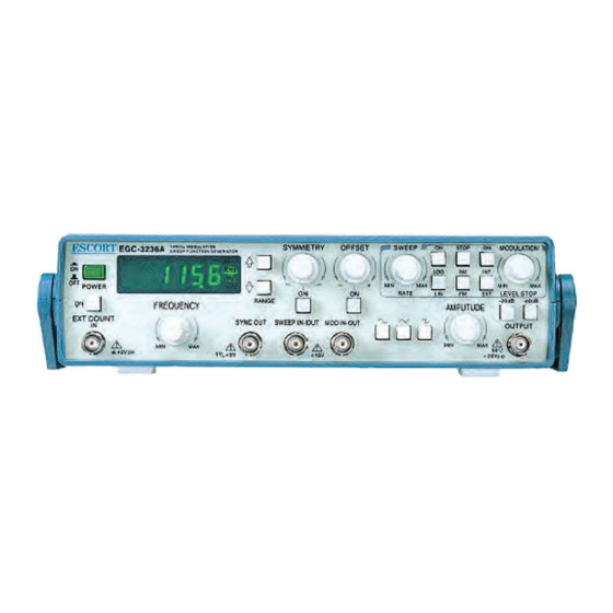
Getting Started Electrical Specifications Front Panel Figure 1 shows the front panel controls, connectors and indicators. POWER SWITCH: To toggle instrument power ON and EXT-COUNTER INPUT: BNC connector is used for the OFF. external signal frequency measurement. The input frequency is from 5Hz to 50MHz. Counter READOUT: A six-digit display that shows frequency generator or external counter. -
Page 11: Rear Panel
Electrical Specifications Rear Panel In addition to line voltage selector, fuse and power cord receptacle VENTILATION FAN: Always keep nothing on the front of fan for better ventilation. POWER CORD SOCKET LINE VOLTAGE SELECTOR AND FUSE HOLDER: To select line voltage and fuse replacement. Preparing For Use Precautions In order to avoid damaging this instrument, make sure that the unit is set to the correct line voltage for... -
Page 12: Reference Operation
Reference Operation This section describes several advanced functions. The variety of swept available from the function generator make it especially useful for such applications as test servo-system or amplifier response, distortion and stability. It can use for FM generator, frequency multiplication, or as a variable, beat- frequency oscillator. -
Page 13: Maintenance
Maintenance Warning! To avoid electrical shock or damaging this instrument, never get water into the meter. Cleaning Before cleaning this instrument, make sure the power is switched in OFF position and the power cord is disconnected from the AC outlet. To clean the meter, wipe the dirty parts with gauze or soft cloth soak with diluted neutral detergent. -
Page 14: Adjustment Procedures
Adjustment Procedures Caution The following instructions are for qualified service personnel only. To avoid electrical shock, do not perform any servicing other than contained in the operation instructions unless you are qualified to do so. Before calibrating and adjusting, make sure that the instrument has warmed up for at least 2 hours. Required Test Equipment The following Table lists the test equipment necessary to perform the adjustments and the maintenance of this instrument. - Page 15 D: Frequency Adjustment F: Function adjustment of Sine wave. Connect the OUTPUT to an external counter. Connect a distortion analyzer through a 50 ohms termination to the OUTPUT and monitor with an Set the controls as follows: oscilloscope also. FUNCTION TRIANGLE Set the FG controls as follows: AMPLITUDE...
-
Page 16: South Australia 257 Grange Road Findon, Sa 5023
South Australia Western Australia Victoria 257 Grange Road Unit 2/17 Casino Street, Mark Kennedy Findon, SA 5023 Welshpool, WA 6016 M: 0430 299 164 P: +61 08 8243 3500 P: +61 08 9353 1943 P: +61 08 8243 3500 F: +61 08 8243 3501 F: +61 08 8243 3501 F: +61 08 9353 4319 E: sales@wavecom.com.au...
Need help?
Do you have a question about the EGC-3236A and is the answer not in the manual?
Questions and answers