MiLOCKS BLEF, CF, DF, TF, QF, XF, ZWF - Entry Deadbolt Lock Manual
- Installation manual (2 pages)
Advertisement
PACKAGE CONTENTS

PARTS LIST:
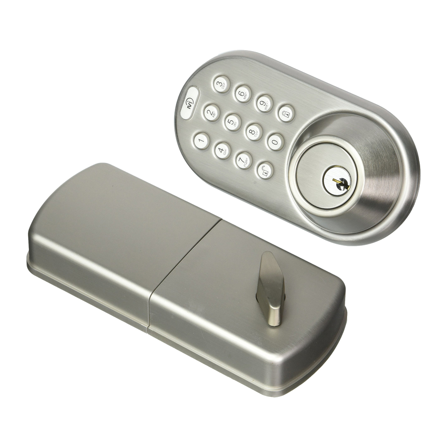
- Front Module
- Back Module
- Strike Plate
- Mounting Plate
- Extendable Latch
- Screws
F1. Mounting Plate Screws
F2. Back Module Screws
F3. Strike Plate/Latch Screws - Traditional Keys
- RF Remote (QF & XF Model Only)
** Illustrations may not be exact representation of product
REQUIRED TOOLS (NOT INCLUDED)

DISCLAIMER:
- Carefully read instructions in their entirety before installing.
- Always use proper safety measures during the install of this product.
- Always have traditional keys on hand in case of electronic failure.
- Only use brand new, popular brand, alkaline non rechargable AA batteries.
- Remove batteries from product when storing for extended periods of time.
- Back Module (B) needs to be protected from weather.
PRODUCT REGISTRATION
Although we hope you never have to deal with a warranty claim during the use of our product, you should submit a product registra on to validate the warranty. This keeps it on record with us so you don't have to save a receipt or record of any kind. Just give us a call and we will take care of you.
REGISTER YOUR PRODUCT AT: www.milocks.com/product-registration/

- Do NOT use rechargable batteries (Li-On, nickel blends, rechargable alkaline).
- Do NOT use non-rechargable zinc blend batteries.
![]()
- Do NOT mix old and new batteries.
![]()
- Do NOT puncture or damage batteries. Electrolyte leakage from the batteries is corrosive and can cause serious harm to the eyes or skin. If swallowed, the electrolyte can be toxic.
![]()
- Do not dispose of batteries in fire as they may explode.
![]()
Please follow your local battery disposal procedure.


Ignoring disclaimer or warnings may cause electrical issues to your MiLocks item. Issues may include: Overheating, leakage, discharge, voltage fluctuations, failed engagement of internal mechanism and bodily harm. MiProducts Corp is not liable for product failures or health issues due to product or battery negligence and/or misuse.
Adjusting Latch Size
Parts: E
For doors with bore holes 2 3/8" (60mm) from door edge, do not extend latch.
For doors with bore holes 2 3/4" (70mm) from door edge, extend latch by:
- Twist Latch
- Extend
- Twist back
(Note: When inserting into door, be sure UP↑ on latch is correctly oriented)

Secure Strike Plate and Latch
Parts: C, E, F3
Note: Latch should be in the UNLOCK position.
- Use Screws (F3) to secure Strike Plate (C) to door frame.
- Use Screws (F3) to secure Latch (E) To door


Front Module Installation
Parts: A, E
- Run Drive Bar (!) through the Cross Slot (!) of the Latch (E).
- Run Connector Wire through bore hole of door.
(!) Be sure drive bar is verticle when inserting into Cross Slot.

** Illustrations may not be exact representation of product. Does not effect installation.

Mounting Plate
Parts: D, F1
On opposite side of door from front module:
(!) The rounded bump of the Mounting Plate (D) should be placed flush with the door.
- Run Drive Bar and Wire Connector through Mounting Plate (D) as shown.
- Use Screws (F1) to secure Mounting plate and Front Module (A).


Connect Wires
Parts: B
- Remove Battery Cover from Back Module before continuing:
- Connect the White Wire Tabs from the Front Module (A) and back Module (B) together.
(!) Before continuing: Back Module (B) should be in the Unlock position by twisting thumb-turn away from Latch (E).
 ** Illustrations may not be exact representation of product. Does not effect installation.
 ** Illustrations may not be exact representation of product. Does not effect installation.
Parts: B, F2
- Insert Drive Bar into Back Module's (B) Cross Slot.
- Secure with Screws (F2).
- Install brand new 4x AA batteries
- Place battery cover back on.
 ** Illustrations may not be exact representation of product. Does not effect installation.
 ** Illustrations may not be exact representation of product. Does not effect installation.
Know Your Program Controls
** Illustrations may not be exact representation of product. Does not effect programming process.

Programing Panel:
Found under battery cover of back module.
C: Clear
S: Set
1|2 Switch: Has two functions,
- The Switch is used to change the direction your lock engages the latch (Depends on right or left door installation).
- Switch needs to be on 2 during any programming of codes.

Keypad:
Mi Logo Button (Top Button): Enables keypad back lighting.
1-9, 0 Buttons: Used to enter numerical key codes.
Lock Button: Electronically engages latch to lock position.
Unlock Button: Has two functions,
- Pressing the Unlock button after entering saved Keypad Code to electronically engage latch to unlock position.
- During programing, the unlock button is used to confirm key codes being set or cleared.
PROGRAM: Add A Code To Lock

PROGRAM: Delete A Code From Lock

PROGRAM: Delete ALL Codes

PROGRAM: Pairing RF Remote (QF or XF Model Only)

PROGRAM: Function Test
If a passcode has not been successfully programmed, the lock will not operate using the keypad. To check if a passcode has been successfully programmed in the memory:
- Manually unlock door lock and open the door. Make sure door is kept open during Function Test.
- Press the LOCK button on the keypad 1 time and listen to the beeps:
- 1 Beep, Engagement: If lock beeps 1 times and latch is engaged successfully, at least 1 code has been saved to lock memory.
- 2 Beeps: If the lock beeps 2 times and latch is not engaged, one of two issues:
- Set 1|2 switch to other number.
- Passcode not properly set. Refer to programming instructions on adding a passcode.
** If issue persists, please contact tech support. **
- Rapid Beeping: If the lock produces a set of rapid beeps and/or partially engages latch, you have low batteries. Replace the batteries with a set of 4 premium "AA" alkaline batteries.
TROUBLESHOOTING
Low Batteries (Most Common Issue): If the lock produces a set of rapid beeps and/or partially engages latch, you have low batteries. To avoid any difficulties during set up, make sure you are using brand new AA alkaline batteries. Using a battery tester is not recommended. Always have traditional keys on hand.
Door Jam Alignment: Make sure the deadbolt and the hole in the door jam line up so that there is minimal resistance or friction on the deadbolt as it extends and retracts from the door.
Driver Bar and/or Thumb-turn Position: In step 3 of the installation, you are instructed to position the driver bar in the vertical position while the deadbolt is retracted. In step 5 of the installation, you are instructed to position the thumb turn according to which side the door latch faces. If these parts are not positioned according to the instructions, you will encounter issues such as the lock only working with the key in the cylinder, a jammed thumb turn, or a key that will not release from the cylinder. The best thing to do is remove the lock from the door and install the lock according to the instructions provided.
Loose Keypad Connection: If not connected securely, the keypad wire harness connection may come loose and cause some of the numbers to operate inconsistently. To confirm your door lock issue is not being cause by a loose keypad connection, press every number on the keypad and confirm every button beeps when pressed.
Unresponsive Keypad Buttons: If some of the numbers are not beeping, remove the back module (part B) and inspect the wires for any pinches or tears. Make sure to check the wires coming from the keypad as well. Disconnect the wire harness and make sure the pins in the male connection are not bent out of alignment. Reconnect your wires and confirm every button on the keypad beeps when pressed. If you are still having keypad issues after following our troubleshooting guide, call us for a replacement under warranty.
PLEASE CONTACT OUR TECHNICAL SUPPORT IF:
- NEED ASSISTANCE INSTALLING OR PROGRAMMING YOUR LOCK
- LOCK IS NOT WORKING PROPERLY AFTER TROUBLESHOOTING
- OR NEED TO FILE A WARRANTY CLAIM
1-800-355-0157
Mon-Fri 9:00am to 5:00pm PST (English & Spanish)
ALTERNATIVELY, FILE WARRANTY CLAIMS AT: www.milocks.com/warranty

Documents / Resources
References
Download manual
Here you can download full pdf version of manual, it may contain additional safety instructions, warranty information, FCC rules, etc.
Download MiLOCKS BLEF, CF, DF, TF, QF, XF, ZWF - Entry Deadbolt Lock Manual
Advertisement


Need help?
Do you have a question about the BLEF and is the answer not in the manual?
Questions and answers