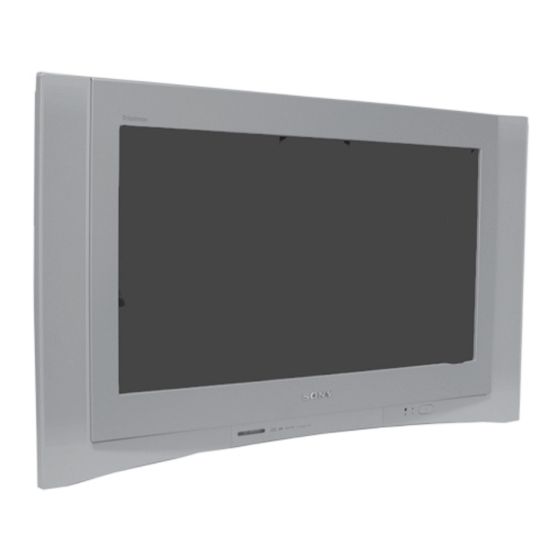
Sony FD TRINITRON KV-28FQ86E Service Manual
Ae-6ba chassis
Hide thumbs
Also See for FD TRINITRON KV-28FQ86E:
- Service manual (78 pages) ,
- Service manual (24 pages) ,
- Service manual (62 pages)
Table of Contents
Advertisement
Quick Links
SERVICE MANUAL
MODEL
KV-28FQ86B
KV-28FQ86E
All manuals and user guides at all-guides.com
COMMANDER
DEST
CHASSIS NO.
RM-945
FR
SCC-Q83T-A
RM-945
ESP
SCC-Q81W-A
MODEL
KV-32FQ86B
KV-32FQ86E
KV-32FQ86K
KV-32FQ86U
KV-32FQ86
- 1 -
AE-6BA
CHASSIS
COMMANDER
DEST
CHASSIS NO.
RM-945
FR
SCC-Q83U-A
RM-945
ESP
SCC-Q81X-A
RM-945
OIRT
SCC-Q82M-A
RM-945
UK
SCC-Q84T-A
RM-945
Advertisement
Table of Contents

Related Manuals for Sony FD TRINITRON KV-28FQ86E


Summary of Contents for Sony FD TRINITRON KV-28FQ86E
- Page 1 All manuals and user guides at all-guides.com AE-6BA SERVICE MANUAL CHASSIS MODEL MODEL COMMANDER DEST CHASSIS NO. COMMANDER DEST CHASSIS NO. KV-28FQ86B KV-32FQ86B RM-945 SCC-Q83T-A RM-945 SCC-Q83U-A KV-28FQ86E KV-32FQ86E RM-945 SCC-Q81W-A RM-945 SCC-Q81X-A KV-32FQ86K RM-945 OIRT SCC-Q82M-A KV-32FQ86U RM-945 SCC-Q84T-A KV-32FQ86 RM-945 - 1 -...
-
Page 2: Table Of Contents
PARTS LIST ARE CRITICAL FOR SAFE OPERATION. REPLACE THESE COMPONENTS WITH SONY PARTS WHOSE PART NE LES REMPLACER QUE PAR DES COMPSANTS SONY DONT LE NUMÈRO DE PIÈCE EST INDIQUÈ DANS LE PRÈSENT NUMBERS APPEAR AS SHOWN IN THIS MANUAL OR IN SUPPLEMENTS PUBLISHED BY SONY. -
Page 3: Caution
Due to the higher melting point of Lead Free Solder the soldering iron tip temperature needs to be set to 370 degrees centigrade. This requires soldering equipment capable of accurate temperature control coupled with a good heat recovery characteristics. For more information on the use of Lead Free Solder, please refer to http://www.sony-training.com - 3 -... -
Page 4: Specifications
All manuals and user guides at all-guides.com . s l . s l . s l . s l . s l e i l . s l n i l t c i n i l i g i i n i - 4 -... - Page 5 All manuals and user guides at all-guides.com y t i WARNING (UK Models only) The flexible mains lead is supplied connected to a B.S. 1363 fused plug having a fuse of 5 AMP rating. Should the fuse need to be replaced, use a 5AMP FUSE approved by ASTA to BS 1362, ie one that carries the mark.
-
Page 6: Connectors
All manuals and user guides at all-guides.com 21 pin connector Pin No Signal Signal level Audio output B Standard level : 0.5V rms (right) Output impedence : Less than 1kohm* Audio input B Standard level : 0.5V rms (right) Output impedence : More than 10kohm* Audio output A Standard level : 0.5V rms (left) -
Page 7: Self Diagnostic Software
All manuals and user guides at all-guides.com AE-6BA SELF DIAGNOSTIC SOFTWARE The identification of errors within the AE-6BA chassis is triggered in one of two ways :- 1: Busy or 2: Device failure to respond to IIC. In the event of one of these situations arising the software will first try to release the bus if busy (Failure to do so will report with a continuous flashing LED) and then communicate with each device in turn to establish if a device is faulty. -
Page 8: General
All manuals and user guides at all-guides.com SECTION 1 GENERAL - 8 -... -
Page 9: Introducing And Using The Menu System
All manuals and user guides at all-guides.com - 9 -... -
Page 10: The Sound Adjustment Menu
All manuals and user guides at all-guides.com - 10 -... -
Page 11: Teletext
All manuals and user guides at all-guides.com - 11 -... -
Page 12: Technical Specifications
All manuals and user guides at all-guides.com - 12 -... -
Page 13: Troubleshooting
All manuals and user guides at all-guides.com - 13 -... -
Page 14: Disassembly
All manuals and user guides at all-guides.com SECTION 2 DISASSEMBLY 2-1. Rear Cover Removal 2-2. Speaker Connector Disconnection => => => => Remove the rear cover fixing screws indicated and pull the Before completely removing the rear cover disconnect the rear cover backwards away from the set. -
Page 15: Service Position
All manuals and user guides at all-guides.com 2-4. Service Position 2-5. G Board Removal Clips To remove the G Board remove the two screws from the To place the chassis in the service position, insert the main middle of the board, release the clips circled and ease the bracket firmly into the T-slot located on the left corner of the board gently away from the support bracket. -
Page 16: Picture Tube Removal
All manuals and user guides at all-guides.com 2-8. Picture Tube Removal WARNING: BEFORE REMOVING THE ANODE CAP High voltage remains in the CRT even after the power is disconnected. To avoid electric shock, discharge CRT before attempting to remove the anode cap. -
Page 17: Bottom Plates
All manuals and user guides at all-guides.com - 17 -... -
Page 18: Set-Up Adjustments
All manuals and user guides at all-guides.com SECTION 3 SET-UP ADJUSTMENTS • When complete readjustment is necessary or a new picture tube Carry out the adjustments in the following order : is installed, carry out the following adjustments. 3-1. Beam Landing. •... -
Page 19: Convergence
All manuals and user guides at all-guides.com Fig.3-4 Align both Purity Purity magnets Purity control magnets magnets to the vertical position Align pips on each magnet 3-2. Convergence (1) Screen centre convergence [Static convergence] Input a dot pattern signal from the pattern generator. Normalize the picture setting. - Page 20 All manuals and user guides at all-guides.com Correction for HMC [Horizontal mis-convergence] and VMC HTIL correction can be performed by adding a THL correction [Vertical mis-convergence] by using the BMC [Hexapole] assembly to the Deflection yoke. magnet. a). HMC correction by BMC [Hexapole] magnet and movement of the electron beam.
-
Page 21: Focus Adjustment
All manuals and user guides at all-guides.com Layout of each control 3-3. Focus Adjustment Receive a television broadcast signal. Normalize the picture setting. Purity magnet Adjust the focus control located on the flyback transformer to BMC (Hexaploe) magnet obtain the best focus at the centre of the screen. V STAT convergence magnet Bring only the centre area of the screen into focus, the magenta- Y-splitting axis correction magnet... -
Page 22: Circuit Adjustments
All manuals and user guides at all-guides.com SECTION 4 CIRCUIT ADJUSTMENTS 4-1. Electrical Adjustments Service adjustments to this model can be performed using the supplied remote Commander RM-945. Programming the Remote Commander for Operation in Service Mode Press and hold the left Mode Select button until the VCR and DVD LED’s flash. - Page 23 All manuals and user guides at all-guides.com Sub Brightness Adjustment Input a Monoscope pattern. Program the Remote Commander for operation in Service Mode. [ See Page 22 ]. Press ‘AUX/VIDEO’ ‘AUX/VIDEO’ 13 on the Remote Commander. Adjust the ‘Sub-Brightness’ data so that there is barely a difference between the 0 IRE and 10 IRE signal levels.
-
Page 24: Test Mode 2
All manuals and user guides at all-guides.com Sub Colour Adjustment 4-2. TEST MODE 2: Receive a PAL colour bar signal. Test Mode 2 is available by programming the Remote Commander for Connect an oscilloscope to Pin 5 of CN7331 [C Board]. operation in Service Mode [ As shown on Page 22 ] then pressing the Program the Remote Commander for operation in Service Mode.
Need help?
Do you have a question about the FD TRINITRON KV-28FQ86E and is the answer not in the manual?
Questions and answers