
Summary of Contents for Move Vibrometer
- Page 1 Vibrometer Instruction Manual Quick installation guide and system operation Important safety, compliance and warranty information...
- Page 2 Move S.p.A. Piazza Cavour 7, 20121 Milan - Italy Via Guglielmo Lippi Francesconi 1256/J, 55100 Lucca - Italy P.IVA: 09887990969 MOVE SOLUTIONS CUSTOMER ASSISTANCE SERVICE Visit the website at www.movesolutions.it for contact information relating to office addresses and telephone numbers.
- Page 3 Instruction Manual English Read manual before product use LICENSE AND COPYRIGHT © 2021 Move S.p.A. All rights reserved. PUBBLICATION Printed in Italy August 2023 NOTICE OF PUBLICATION The information contained in this manual may be subject to change without notifica- tion.
-
Page 4: Table Of Contents
........Move Cloud Platform™ .......... - Page 5 � � � � � � � � � � � � � � � � � � � � � � � � � � � � � � � � � � � � � � � � � � � � � � Vibrometer...
-
Page 6: Warnings
For the correct and safe operation of the product, it is recommended to read and follow the instructions in this manual. Great attention should be paid to the following warnings. Move Solutions shall not be held responsible for inconveniences, damage or malfunctions due to lack of com- pliance to the prescriptions and suggested use in this manual. - Page 7 In case of deterioration or loss of this manual, a compliant copy may be requested by the customer from the manufacturer. For increased security, we suggest that you keep a copy of this manual in a place where it cannot be damaged or lost. Vibrometer...
-
Page 8: Fcc Compliance
FCC Compliance This device complies with part 15 of the FCC Rules. Operation is subject to the following two conditions: • This device may not cause harmful interference • This device must accept any interference received, including interference that may cause undesired operation. Changes or modifications not expressly approved by the party responsible for com- pliance could void the user’s authority to operate the equipment. -
Page 9: Ised Compliance
This equipment complies with Industry Canada radiation exposure limits set forth for an uncontrolled environment. Cet équipement est conforme à l’exposition aux rayonnements Industry Canada limites établies pour un environnement non contrôlé. Vibrometer... -
Page 10: Symbols And Provisions Used In The Documentation
Bold Bold text highlights an important point or keywords for understanding the context. Italic Text in italics is used for specific names for sensors, options of the Move Cloud Platform, or chapters of this manual. Instruction manual - EN... -
Page 11: Glossary
Alarm Threshold • this threshold is applied to events on the Move Cloud Platform. If the threshold is exceeded and email alarms are configured an email notification is sent. Vibrometer... -
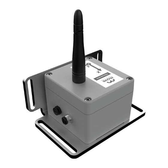
Page 12: General Description
General description The triaxial Vibrometer can measure the velocity of the point where it is installed, providing frequency and amplitude analysis of vibrations. With the use of Vibrometer devices it is possible to highlight vibrations in structures, mainly induced by external factors, and monitor their risks. - Page 13 The Vibrometer is part of the Move Solutions range of LoRaWAN products for moni- toring purposes; as such, it needs a LoRaWAN gateway in its range (such as the Move Solutions Gateway Pro) to connect to the Move Cloud Platform. When the sensor is connected to the platform, the settings and data can be personalized to fit the user’s...
-
Page 14: Technical Data
Technical Data Operation Operating temperature range -40°C to +80°C IP rating IP67 1 LiSOCl2 battery Batteries (suggested: EVE ER34615EHR2) Battery connector JST EHR-2 Radio coverage 1 km in line of sight with gateway Maximum radiated power < +17 dBm 868 MHz in EU and UK, Transmission Frequency 902 MHZ in US and Canada This information is strictly dependent on environmental parameters such as humidity,... - Page 15 2 seconds Internal storage 2000 acquisitions Additional calibration may be necessary for compliance with some regulations. Ca- libration service available on request. Mechanical Dimensions (with plate and antenna) 123 x 95 x 145 mm Material Alloy GD-AlSi12 Weight 1.1 Kg Vibrometer...
-
Page 16: What's In The Box
What’s in the box The Vibrometer is shipped inside a cardboard box. On the side of the box, a label is affixed with the EUI and Serial Number of the product. The EUI is very important as it identifies the sensor on the Move Cloud Platform™. - Page 17 The IP rating of the product is guaranteed only after the antenna is screwed tightly on and the serial connector has a cable connected or the supplied lid on. DO NOT loosen or tighten the screws of the Vibrometer as this could • alter the product’s IP rating.
-
Page 18: Quick Guide To Installation
NOTE • The axes referenced on the Move Cloud Platform™ are the same as indicated on the device’s labels. It is strongly advised to keep a consistent orientation of the vibrometers on the structure, unless differently intended, and to always take note of the installation position of each vibrometer for future reference. - Page 19 CHANGING PLATE ORIENTATION The installation plate allows the Vibrometer to be rotated 90, 180 or 270 degrees around the Z axis relative to its factory position. To change the sensor’s orientation: ibrometer ixing plate Remove the two screws on the bottom of the plate.
-
Page 20: Installation
6.2 Installation IMPORTANT Make sure the surface where the Vibrometer is going to be installed does not have asperities and protrusions. Close, stable and tight contact of the device with the surface is crucial to detecting accurate data. Using the installation plate as Drill two holes in the mounting reference, mark the chosen spot. - Page 21 If the gateway is already running, you can start checking your data on the Move Cloud Platform™ within a few minutes. Otherwise, a maximum time of 30 minutes after the installation of the gateway is required before the sensor can be viewed on the platform.
-
Page 22: Maximizing Radio Performance
If this cannot be avoided, it is best to keep the two antennas perpendicular to one another. Keep the Vibrometer and the gateway in line of sight as much as possible, as obstacles along the path of the signal could have a negative impact on the radio link. - Page 23 Similarly, keep as clear as possible of high voltage power cables, radio and tv antennas and any other source of unwanted electromagnetic disturbance. Use the hardware supplied with the Vibrometer to fix it to the wall, floor, or ceiling. WARNING •...
-
Page 24: Move Cloud Platform
To access the settings of your Vibrometer, go to Settings in the side navigation menu. Select Vibrometer in the side bar, and a list of all the vibrometers on your structure will appear. From this page you will have various tabs available. -
Page 25: Data Visualization
In Threshold triggering mode, data acquisition is performed only when the input velocity exceeds the Working Threshold. • In the Cadence tab, you can choose how often data is sent to the Move Cloud Platform™ (available only in Time triggering mode). •... - Page 26 In the Vibrational Tool page the user can select a custom date range to visualize • the data from the sensor. Available data in this page: • If PPV mode is enabled, the PPV graph shows the PPV computed on selected axes for the last day.
-
Page 27: Acquired Data
Acquired data The vibrometer samples data with a sampling frequency of 512 Hz, and has a -3dB bandwidth of 0.5 Hz (2 order high-pass) to 100 Hz (2 order low-pass). Sample resolution is 16 bits with a full scale that can be selected between 50 mm/s and 100 mm/s. - Page 28 NOTE • not all the combinations of event acquisition mode and regulation are allowed. Event acquisition modes are: Programmed data acquisition: the sensor sends events at regular intervals. If • the event’s velocity exceeds the working threshold, the event (waveform included) is saved to the storage memory.
- Page 29 If at least two axes are selected and the PPV mode is disabled, the velocity is computed at the maximum among the selected axes (considered as its absolute value): • All axes selected: • 2 axes selected: This mode allows both Programmed data acquisition and Threshold data acquisition. Vibrometer...
- Page 30 The sensor implements always-on data acquisition: it samples the 3-axis velocity con- tinuously in between the transmission of two events. This means that there is virtually no downtime in the acquired data, and even occasional vibrations of the structure are captured.
- Page 31 Working threshold. For example, we can assume a maximum of 23 mm/s for the monitored quantity. Since this is above the 20 mm/s Working Threshold set for the sensor, this would mean that the event will be saved into the sensor’s storage memory. Vibrometer...
-
Page 32: Maintenance
In this event, only use the prescribed batteries. For information on how to provision said batteries, please contact a Move Solutions re- presentative. If the prescribed batteries are unavailable, or provisioning is not possible, consult a Move Solutions representative to find a viable alternative. -
Page 33: Overall Dimensions
Therefore, it is essential to rely on the numerical measurements provided alongside the drawings for accurate dimensions. The following measurements are expressed in millimeters (mm). Front view Right view 123,0 91,0 Ø6,5 Upper view Ø6,5 Vibrometer... - Page 34 Dismount the Vibrometer and move it in a location closer to the gateway and wait up to one day. If the Vibrometer goes back online, it probably means that the radio path between it and the gateway is suboptimal, and action needs to be taken.
- Page 35 The Vibrometer might be configured in Threshold triggering mode with a working threshold that’s too high for the data the Vibrometer is sensing. Check that the vibro- meter’s mechanical coupling to the structure is correct. If the mechanical coupling is correct the velocity data might be too low compared to the selected working threshold: in this case, you can set a lower threshold to collect more data points.
- Page 36 MOVE SOLUTIONS CUSTOMER ASSISTANCE SERVICE Visit the website at www.movesolutions.it for contact information relating to office addresses and telephone numbers. Instruction manual - EN...
- Page 37 LICENSE AND COPYRIGHT © 2023 Move S.p.A. All rights reserved. PUBBLICATION Made in Italy 08/2023 Vibrometer...
- Page 38 Move S.p.A. Piazza Cavour 7, 20121 Milan - Italy Via Guglielmo Lippi Francesconi 1256/J, 55100 Lucca - Italy P.IVA: 09887990969...
Need help?
Do you have a question about the Vibrometer and is the answer not in the manual?
Questions and answers