
Summary of Contents for Accorroni AS COND
- Page 1 Floor standing hot air generators indoor/outdoor gas condensing AS COND - AS COND EX...
-
Page 2: Table Of Contents
PURPOSE ...................................... 3 GENERAL INFORMATION AND PRECAUTIONS ........................5 PLATE OF THE CHARACTERISTICS OF THE WARM AIR HEATER ..................9 DATA SHEET WARM AIR HEATER series: “AS COND” "AS COND EX" ................19 ECODESIGN ....................................21 FUNCTION DESCRIPTION ............................... 22 INSTALLATION .................................. -
Page 3: Purpose
PURPOSE Machine we mean the warm air heater complete with its accessories This manual is intended for operators and specialized personnel and provides important information and warnings on safety in the installation, commissioning, use and maintenance of the machine, to allow it to be used correctly. Inside you will find the following descriptions and information: a functional description of the machine and of each of its parts machine safety information... - Page 4 This manual is an essential and integral part of the machine, therefore it must be followed, even in the case of transfer of ownership or to another facility, and must be stored with care. In case of damage or loss, another copy must be requested from the manufacturer. The operator and specialized personnel are required to read and understand the contents of this manual.
-
Page 5: General Information And Precautions
GENERAL INFORMATION AND PRECAUTIONS This machine is suitable for the following uses: a) Direct heating of the blown air through its own fan unit. The heat exchange occurs by contact between the external walls of the combustion chamber / heat exchanger and the air that passes through it. - Page 6 Information on safety and prevention The machine has been designed and built in compliance with the standards and directives in force, applying the known technical safety rules and providing for all potential dangerous situations. However, it is necessary to take into account that careless and clumsy use of the machine can cause situations of danger of death for the user or third parties, as well as damage to the machine itself or to other assets.
- Page 7 CONSTRUCTION EXAMINATION AND SAFETY REQUIREMENTS The warm air heater consists of an aluminium frame and an external panelling in pre-painted sheet metal: the panels are internally insulated with a glass wool mat. In the heating section we find a combustion chamber and a heat exchanger. In this area, the insulating mat is protected against the danger of overheating by a galvanized sheet cover.
- Page 8 Other essential safety requirements Electrical equipment. After the various assembly stages, all warm air heaters are subjected to the following electrical checks to verify compliance: visual check of the electrical circuit and tightening of the connections; continuity of the earth circuit; insulation resistance test;...
-
Page 9: Plate Of The Characteristics Of The Warm Air Heater
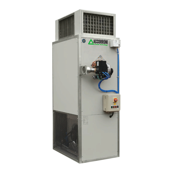
Qui di seguito viene riportato un facsimile di tale targhetta. A facsimile of this plate is shown below. A2B Accorroni E.G. s.r.l. Via dʼAncona, 37 - 60027 Osimo (An) Tel. 071.723991 www.accorroni.it - a2b@accorroni.it... - Page 10 CONSTRUCTION CHARACTERISTICS COMPOSITION OF THE “AS COND” VERSION Models from 50 to 65, with single-phase motor, and direct driven fan Air outlet 2) Rear smoke box door 3) Burner 4) Burner anchor plate 5) Centrifugal fan 6) Air inlet grille...
- Page 11 Models 250 and 600, with three-phase motor and transmission driven fan Air outlet 2) Rear smoke box door 3) Burner 4) Burner anchor plate 5) Centrifugal fan 6) Air inlet grille 7) Condensate drain with siphon 8) Smoke exhaust connection 9) Rear smoke box 10) Heat exchanger 11) Combustion chamber...
- Page 12 WEIGHTS and DIMENSIONS "AS COND" SERIES Weight in [kg] and dimensions in [mm]. connection Connection of the air outlet duct Connection of the air inlet duct The air inlet grille is on the LEFT up to model X200 and on the RIGHT from model X250 up to model X600.
- Page 13 The warm air heater is supplied with screws, plates, brackets and self-adhesive gaskets for the versions XO e XEO. ASSEMBLY OF THE BURNER PROTECTION CABIN FOR "AS COND EX 600" WARM AIR HEATERS Proceed as follows: place the edge (4) of the cabin on the upper profile of the warm air heater, on the burner side;...
- Page 14 17) External insulated panels 18) Burner cabin for protecting burner and electric components Models from “AS COND EX 80” to “AS COND EX 200” with three-phase motor and transmission driven fan Air outlet 2) Rear smoke box door 3) Burner...
- Page 15 Models “AS COND EX 250”, “AS COND EX 300” with three-phase- motor and transmission driven fan Air outlet Rear smoke box door Burner Burner anchor plate 5) Centrifugal fan 6) Air inlet grille 7) Condensate drain with siphon 8) Smoke exhaust connection...
- Page 16 WEIGHTS and DIMENSIONS "AS COND EX" SERIES Weight on [kg] and dimensions on [mm]. Connection Connection of the of the air air outlet duct inlet duct The air inlet grille is on the LEFT till model XE200 and on the RIGHT from model XE250 up to model XE600.
- Page 17 STANDARD HEAD FOR DIRECT AIR DISTRIBUTION WARM AIR HEATERS OF THE "AS COND EX " Air blown and dimensions in mm with horizontal and vertical fin vents on three sides of the nozzles. Air blown in m. n° of nozzles MOD.
- Page 18 FILTER BOXES ON AIR INLET DELIVERY WARM AIR HEATERS OF THE "AS COND " and "AS COND EX " SERIES Pressure Filters (1) MOD. drop (2) [mm] [Pa] AS COND 50 1x640x810x48 XE50 2x500x400x48 AS COND 80 1x910x695x48 1020 1x625x500x48...
-
Page 19: Data Sheet Warm Air Heater Series "As Cond" "As Cond Ex
DATA SHEET WARM AIR HEATER series “AS COND" "AS COND EX" THERMAL PERFORMANCE Mod. Rated heat input, Qnom 61,1 98,5 Rated heat output, Pn 59,8 73,0 96,3 116,6 178,6 201,8 234,2 Thermal efficiency at rated heat input, Pn 97,9 96,1... - Page 20 DATA SHEET WARM AIR HEATER series: “AS COND” “AS COND EX” THERMAL PERFORMANCE X425 X500 X600 Mod. Rated heat input, Qnom Rated heat output, Pn 428,4 495,5 592,8 Thermal efficiency at rated heat input, Pn 100,8 99,1 98,8 Heat input at 50% of the rated heat input...
-
Page 22: Function Description
FUNCTION DESCRIPTION Heating mode operation Heating mode On the electrical panel the main switch must be in position -1- and the commutator in position -HEATING-. At each request for heat from the room thermostat, the burner starts its self-test and pre-cleaning cycle at the end of which combustion begins. - Page 23 MODULATION REGULATOR CAREL TYPE CLIMA ( read his instructions supplied with the heater) The burner, of modulating type, is controlled (during flame modulation phases) by the ambient terminal device type “Clima”, supplied with the heater, with an air sensor NTC in it. The “Clima”...
- Page 24 INSTALLATION INSTRUCTIONS This part of the manual is reserved for the legally required installer. Warm Air Heater Location – Distances The warm air heater shall be installed on a solid horizontal foundation in accordance with the requirements of Ministerial Decree 08-11-2019 and other applicable legislative provisions, rules and regulations that the installer CAUTION is required to be familiar with.
- Page 25 Check dimension B also according to the removability and maintenance of the smoke outlet. Flue Fig 1 Minimum distance of the heater from walls and ceiling scheme Burner PLAN VIEW “AS COND - AS COND EX”...
-
Page 26: Installation
INSTALLATION The installation of the machine must be carried out by qualified personnel with the requirements of the law and in accordance with the standards, laws and regulations in force. Temperature The operating temperatures of burner and electric parts are: Ø... - Page 27 The electrical installation must be carried in accordance with laws and regulation in force, as well as IEEE standards. Electrical insulation of cables must be compliant with IEC 60227 or IEC 60245. The warm air heater is delivered with all internal electrical connections already made with the exception of the general power supply and the CAREL "Clima"...
- Page 28 Smoke exhaust / combustion air intake The X series warm air heaters are suitable for the following flue gas exhaust / combustion air intake configurations: • from model 50 to model 300 and variants: • B23; • C13, C33, C53, (sealed type systems) •...
-
Page 29: Table Of A2B Accorroni Pipes And Elements For Flue
The manufacturer guarantees the machine performance if are used pipes and elements that are supplied by it, that can be find in the table at chapter TABLE OF A2B ACCORRONI PIPES AND ELEMENTS FOR FLUE. The installer can use other elements but they must be homologated and the pressure losses can’t be superior then the ones in the table. - Page 30 SMOKE EXHAUST / COMBUSTION AIR INTAKE CONFIGURATIONS from mod. 50 to mod. 300 ariants AS COND 50 / 100 AS COND 150 / 300 In Configuration B23 in the X-XO-XR versions, it is possible to use the Collar (1) for the intake of combustion air in the room.
-
Page 31: Table Of Pipes And Elements For Fume Exhaust Approved (Poced)
TABLE OF PIPES AND ELEMENTS FOR FUME EXHAUST APPROVED (POCED) AND RELATED PRESSURE DROP MODEL Available pressure (Pa) for flue and combustion air intake PIPES DESCRIPTION Pressure drop in CMT pipe for length unit Pa/m (a) Flue Rigid pipe Ø 100 mm -Length 1 m Combustion air intake Flue Rigid pipe Ø... - Page 32 TABLE OF PIPES AND ELEMENTS FOR FUME EXHAUST APPROVED (POCED) AND RELATED PRESSURE DROP MODEL Available pressure in Pa for exhaust fumes PIPES DESCRIPTION Pressure drop in CMT pipe for length unit Pa/m (a) Flue Rigid pipe Ø 200 mm -Length 1 m Combustion air intake Rigid pipe Ø...
- Page 33 FLUE AND COMBUSTION AIR INTAKE ELEMENTS(POCED) ELEMENT DIMENSIONS DESCRIPTION “T6” CHINESE HAT” “T20” WEATHERPROOF TERMINAL 90° MOULDED BEND 90° T UNION 45° MOULDED BEND 5/30° ADJUSTABLE FLASHING (“T7”) WINDPROOF WALL TERMINAL (“TR”)
- Page 34 Calculation of the combustion smoke weight We propose the equation for calculating the combustion smoke weight based on the kW of methane burned: X = 1,623 Y X = combustion smoke weight (kg) Y = kW burned Connecting the condensate drain The warm air heater is provided with a condensate drain pipe, positioned in the bottom part of gas box, which drains the condensate produced in the heat exchanger.
- Page 35 Fig.8 Trap with closed piping and trap with open piping Condensing water produced by "L" Series warm air heater Mod. Condensing 1,85 water lt/h ASSEMBLY OF DIRECT AIR DELIVERY PLENUM The plenum, if any, must be assembled as described on chapter PLENUM of this manual; it is recommended to apply silicone sealant on contact surfaces.
-
Page 36: Tri Thermostat
Perform a combustion analysis. 1) In the combustion analysis of the warm air heater, combined with a modulating burner, the combustion analysis must be done both at Qnom (nominal heat input), and at Qmin (minimum heat input). The combustion, efficiency and hygiene values obtained, including those of NOx, must be recorded at these two thermal flows. - Page 37 automatic stop the burner in case the average air outlet temperature overheat above the pre- set value imposed by the regulation. The set point at 100°C, is fixed by the manufacturer. This set point must not be changed to avoid the overheating of the warm air heater.
- Page 38 Make sure that the manual-reset LIMIT2 is not activated due to: Ø Low air flow rate, caused by obstructions and obstacles in the air exhaust/distribution system Ø Clogged air filters (if installed) Ø Heater stopped using the master switch or owing to a power failure during operation Ø...
-
Page 39: Electrical Diagrams
ELECTRICAL DIAGRAMS... - Page 41 AS COND EX 250...
- Page 42 AS COND 300 - 600...
- Page 43 MAINTENANCE Before doing any maintenance the machine must be disconnected from power supply using the general switch on the frontal panel of the electric board (positioned on machine). Close adduction of the fuel WARNING The warm air heater and the burner must be serviced by an authorised service centre or by qualified personnel, in compliance with the requirements set forth by law.
- Page 44 Check that the combustion chamber is not damaged. Check that the seal of the burner supporting plate and the relevant seal on the nozle are in good condition; if not, replace them with seals having the same code. When mounting back the burner (4) check the tightening of the bolts on the burner plate. Note: All seals are asbestos-free and compliant with EC standards.
-
Page 45: Table Of Minimum Maintenance Intervals
TABLE OF MINIMUM MAINTENANCE INTERVALS MINIMUM FREQUENCY TYPE OF OPERATION Clean air filters, if installed, if they are clogged. Every day Checking the perfect fixing of the fan section parts. Once every 80 hours of working time Once every 80 hours of working time Check the burner plates bolts tightening. -
Page 47: Annexes
ANNEXES MANUAL “Clima” CAREL for the modulation of burner Clock digital proportional temperature regulator. Timer and real-time clock for day and night operation. Delivered with the warm air heater series X and variation, or with roof top AMC..XR..fitted with modulating burner RX General features “CLIMA”... - Page 48 • Close the instrument with the opposite movement, making sure the flat connection cable does not hinder the operation. • To ensure electrical safety (EN60730-1), insert the plastic tab and tighten the screw to stop the instrument from opening (see Fig. 2). SERIAL CONNECTION OPTION To connect the instrument to the supervisor serial line, the accessory code IROPZ48500 is required.
- Page 49 From the main menu decreases the value of set point displayed in the large field. From the other menus displays the variables or the parameters or alternatively changes the value if first pressing SET. Important: the operating mode can be changed with the instrument on or off. When the mode is changed, the user is asked whether to use the default parameters for that mode.
-
Page 50: Important Warnings
- Use Terminal tightening torque of 4 Lb-In when green (PTR) terminal block is used or 7 Lb-In when black (SAURO) terminal series is used. WARNING: All connections, except for the relays, must be connected to low voltage circuits with reinforced insulation. IMPORTANT WARNINGS The CAREL product is a state-of-the-art product, whose operation is specified in the technical documentation supplied with the product or can be downloaded, even prior to purchase, from the website www.carel.com. - Page 51 MOST IMPORTANT PARAMETERS TO BE SET BY THE INSTALLER We remember that: - parameters dFA e dSA are factory set and must not be changed by the installer/customer, iif not agree with the manufacturer of the warm air heater - parameter rtC real time must be set by the installer parameters SLP, dAy, nlt and relevant ambient temperature Set Point T, winter, summer, day, night : can be modified b the installer, from the default value factory set, see table of parameters.
- Page 56 A2B Accorroni E.G. s.r.l. Via d’Ancona, 37 - 60027 Osimo (An) - Tel. 071.723991 web site: www.accorroni.it - e-mail: a2b@accorroni.it...
Need help?
Do you have a question about the AS COND and is the answer not in the manual?
Questions and answers