Table of Contents
Advertisement
Quick Links
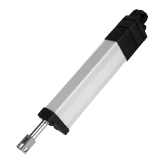
Linear Actuator RA 60 K
Max. lifting force 300 to 600 N, stroke from 100 to 200 mm,
Version with limit switch or stroke measuring system
Table of contents
1
Description of the product
2
Validity of the documentation
3
4
5
6
7
8
9
10
11
12
13
14
Römheld GmbH • Postfach 1253 • 35317 Laubach • Germany • Tel.: +49 (0)6405 / 89-0 • Fax: +49 (0)6405 / 89-211
www.roemheld-gruppe.de
Subject to change without notice! Translation of the original German document
1
Description of the product
Linear actuators RA 60 K consist of a direct current drive (volt-
age see technical characteristics), whose drive energy is trans-
ferred over a planetary gear and a spindle lifting gear to the
pushing rod.
The generated lifting force is available as push and pull force.
Linear actuators without stroke measuring systems are
equipped with internal limit switches. These avoid unintended
overrun and overload of the mechanical stop positions.
The end positions of linear actuators with stroke measuring
system are definable by the signal of the stroke measuring sys-
tem.
The sturdy design with code class IP69K guarantees a trouble-
free function also in rough operating conditions.
Linear actuators are maintenance free and can be operated
with a duty cycle of up to 15%.
Version with limit switches
The version with limit switches has 2 integrated sensors, which
automatically switch off the motor as soon as the upper or
lower stroke end position is obtained. This guarantees that the
linear actuator does not mechanically push against the stop.
Version with stroke measuring system
The version with absolute stroke measuring system is equipped
with a linear potentiometer. A slider at the pushing rod pro-
1
duces a signal at the potentiometer, that is proportional to the
position of the pushing rod. This signal can easily be evaluated
1
by a priority control and is permanently available. Referencing
2
is not required. Due to the direct connection of the absolute
stroke measuring system to the pushing rod, one gets a precise
2
stroke information with slight backlash. This linear actuator is
equipped with a potentiometer and a subsequent amplifier that
2
generates a standardised output signal independent of the
2
stroke length. With the stroke measuring system, control-ori-
ented applications and the compound of several linear actua-
3
tors in synchronism can be realised.
4
2
Validity of the documentation
5
5
6
Part no.: F2-XX-XX-1-C-AS3A (with stroke end disconnec-
6
tion)
6
7
Operating Manual
BA_L4202_EN
Issue 11-2016
1 / 7
Advertisement
Table of Contents

Related Manuals for Roemheld RA 60 K

Summary of Contents for Roemheld RA 60 K
-
Page 1: Table Of Contents
Version with limit switch or stroke measuring system Description of the product Linear actuators RA 60 K consist of a direct current drive (volt- age see technical characteristics), whose drive energy is trans- ferred over a planetary gear and a spindle lifting gear to the pushing rod. -
Page 2: Target Group Of This Document
• Use the ROEMHELD product only in perfect technical con- dition. An expert is somebody who has due to its professional educa- •... -
Page 3: Installation
The product must never be opened. At the product no Note changes must be made, except the ones expressly men- RA 60 K with limit switches cannot be operated in synchronism. tioned in the operating instructions! 7.2.2 Version with stroke measuring system The use of these products is not admitted: •... -
Page 4: Start Up
Operating Manual BA_L4202_EN 2. Prepare the user's construction to mount the product. Pay Note attention to sufficient freedom of motion. The version with (absolute) stroke measuring system is 3. Connect the product with the fork head at the front ant at equipped with a linear potentiometer. -
Page 5: Maintenance
Operating Manual BA_L4202_EN The product must be completely connected to the user's Service life control as per the corresponding circuit diagram and the us- The service life is designed for 20,000 cycles (extending/re- er's terminal diagram. tracting). If the above requirements are not met, the product must not be 10 Trouble shooting put into operation. -
Page 6: Technical Characteristics
Operating Manual BA_L4202_EN In the case of a current consumption exceeding 5 A the user's 10.1 Repair control must switch off the product after 10 sec. at the latest. WARNING NOTE Injuries, material damages or malfunctions! • The product must never be opened. At the product no Specifications changes must be made, except the ones expressly men- •... -
Page 7: Declaration Of Incorporation
This declaration of incorporation applies to the following prod- ucts: This operating manual is valid for linear actuators of the follow- ing types: RA 60 K – 12 V DC Part no.: F2-XX-XX-1-C-AS3A (with stroke end disconnec- tion) Part no.: F2-XX-XX-1-C-AS3A (with stroke measuring sys-...
Need help?
Do you have a question about the RA 60 K and is the answer not in the manual?
Questions and answers