Table of Contents
Advertisement
Quick Links
Advertisement
Table of Contents

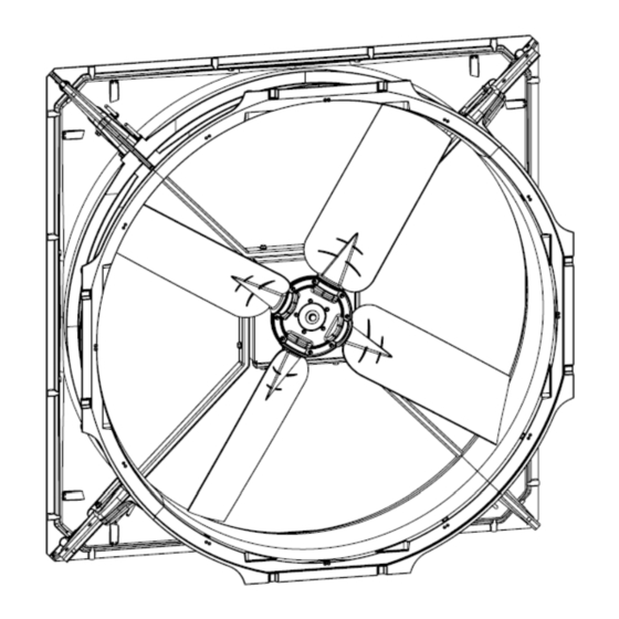
Summary of Contents for MS Schippers WA 1400
- Page 2 © Copyright 2014 Niets uit deze uitgave mag worden verveelvoudigd en/of openbaar gemaakt worden door middel van druk, fotokopie, microfilm, geluidsband, elektronisch of op welke wijze dan ook zonder voorafgaande schriftelijke toestemming van de firma Schippers Europe b.v.
-
Page 3: Table Of Contents
Contents Checklist components General recommendations - Before start assembly fan - Handling - Machine features - Identification data - During installation Cable connection First start Electrical connections - Power supply - Signal Connection scheme - Three phase General connections scheme Connection diagram MS Fan Controller Connectors pin legend - Supply connector pin legend... -
Page 4: Checklist Components
Checklist components... -
Page 5: General Recommendations
General recommendations Before start assembly fan: read instruction manual and understood it completely. Handling: Fan is heavy,so before moving must be checked to have all right equipment in order to avoid accident to people or environment,person working with fan must be informed and formed in order to be able to use right equipment according to local law Machine features: I.IP 65 motor protection grade... -
Page 6: During Installation
During installation: Pull always the yellow wire ( Modbus A) and the Green wire (Modbus B) down to the switchboard (to connect with the fan). Write down the serial number and Modbus address of each motor in a diagram, as well as their location (so that each machine can be uniquely identified) in the event of maintenance.. -
Page 7: Cable Connection
Cable connection... -
Page 8: First Start
First start After having assemble complete fan ,connected power and controler lines,give power to machine and wait about 30 seconds until it start to run,because machine need 30 seconds to autoset all parameters. ATTENTION : All blades must be fitted to enable the motor to start. After that check following: No rotation unbalancing due to wrong components assembly. -
Page 9: Electrical Connections
Electrical connections POWER SUPPLY : The power supply line is composed as follows: A power supply panel supplied via a dedicated 3F+N+E 200-480V 50/60 Hz line provided upstream of a suitable MT (magnetotermic protection) and a class A differential protection with a sensitivity of at least 300mA, the line must be constructed with a cable according to the load present. -
Page 10: Connection Scheme
Connection scheme... -
Page 11: General Connections Scheme
General connections scheme... -
Page 12: Connection Diagram Ms Fan Controller
Connection diagram MS Fan Controller... -
Page 13: Connectors Pin Legend
T-piece not included, installer can loop through via a junction box. Number of fans to loop through The installer knows this and it depends on the electricity group. Power is not supplied via the fan controller. 400V is applied via the isolating switch. Only the 0-10V signal comes from the fan controller. Connectors pin legend...
Need help?
Do you have a question about the WA 1400 and is the answer not in the manual?
Questions and answers