
Subscribe to Our Youtube Channel
Related Manuals for MasterForce 2500194ME

Summary of Contents for MasterForce 2500194ME
- Page 1 80V BRUSHLESS 21" SELF-PROPELLED MOWER 270-1145 2500194ME LMB408 OPERATOR’S MANUAL CAUTION To Reduce The Risk Of Injury, User Must Read And Understand Operator’s Manual. Save These Instructions For Future Reference.
-
Page 2: Table Of Contents
TABLE OF CONTENTS Safety Symbols ......................Page 2 Safety Instructions ...................... Page 3 Overview ........................Page 8 Assembly ........................Page 9 Operation ........................Page 12 Maintenance ......................Page 14 Troubleshooting ......................Page 15 Exploded View ......................Page 17 Notes ........................Page 18 Warranty ........................ -
Page 3: Safety Symbols
SAFETY SYMBOLS Some of the following symbols may be used on this product. Please study them and learn their meaning. Proper interpretation of these symbols will allow you to operate the product better and safer. Symbol Name Designation / Explanation Volts Voltage Amperes... -
Page 4: Safety Instructions
SAFETY INSTRUCTIONS The purpose of safety symbols is to attract our attention to possible dangers. The safety symbols, and the explanations with them, deserve your careful attention and understanding. The symbol warnings do not by themselves eliminate any danger. The instructions and warnings they give are no substitutes for propper accident prevention measures. - Page 5 SAFETY INSTRUCTIONS IMPORTANT SAFETY regular reference. INSTRUCTIONS • Do not use the lawn mower for any job except that or which it is intended. Your lawn mower has been designed to perform R E A D A L L I N S T R U C T I O N S only one job: cut grass.
- Page 6 SAFETY INSTRUCTIONS the lawn mower when you are tired. replacement parts. This will ensure that the safety of the product is maintained. • Always wear safet y glasses or safet y g o g g l e s d u r i n g o p er at i o n a n d w h i l e •...
- Page 7 SAFETY INSTRUCTIONS SLOPE OPERATION • Periodically inspect safety devices and cords for damage. If damaged do not Slopes are a major factor related to slip-and- operate the unit until it has been repaired by an authorized service professional. fall accidents, which can result in severe •...
- Page 8 • Customer Service for assistance. • Never operate the mower without proper guards, plates, or other safety protective devices in place. • Use only Masterforce Batteries: BAB728. • Use only Masterforce Charger: CAB809. SAVE Page 7...
-
Page 9: Overview
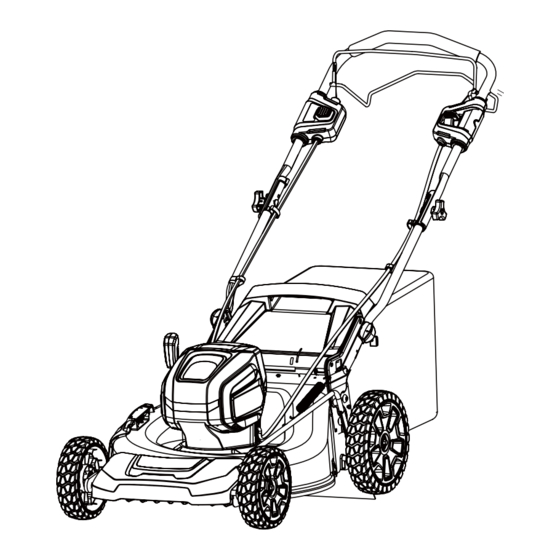
OVERVIEW Bail switch Start button Self-propel lever Upper handle Speed control button Lower handle Battery door Height adjustment lever Grass catcher Side discharge cover Side discharge chute Mulch plug SPECIFICATIONS Type Cordless, battery operated No load speed 2800 RPM Height adjustments 1 3/8 - 3 3/4”... -
Page 10: Assembly
ASSEMBLY UNPACKING INSTALL THE UPPER HANDLE FIG. 2 This product requires assembly. • Carefully remove the product and any accessories from the box. Make sure that all items listed in the package contents Upper section are included. Handle • Inspect the product carefully to make sure Bolts Knobs no breakage or damage occurred during... - Page 11 ASSEMBLY 5. Close the rear discharge door. CAUTION When you use the side discharge chute, • Do not install the grass catcher. INSTALL THE MULCH PLUG • Keep the mulch plug installed. FIG. 4 1. Open the side discharge door and hold it. Rear Discharge Door 2.
- Page 12 ASSEMBLY INSTALL THE BATTERY PACK REMOVE THE BATTERY PACK FIG. 7 FIG. 8 Battery Pack Battery Pack Battery Door Battery Door Battery Release Button Safety Key Safety Key 1. Open the battery door. WARNING 2. Remove the safety key. • If the battery pack or charger is dam- 3.
-
Page 13: Operation
OPERATION a certain temperature/current. Re-setting WARNING the protector requires both cool down be- Wear eye protection low the calibration point and removal of during operation. power supply. When the protection hap- pens, the operator should release the self- START THE MACHINE propel bail lever immediately ,then restart self-propel operation after at least 30 min- utes. - Page 14 OPERATION unhook it from the door rod. 5. Close the rear discharge door. 6. Empty the grass catcher. OPERATE ON SLOPES WARNING Do not mow on the slopes with incline more than 15°. If you are not comfortable, do not mow on a slope.
-
Page 15: Maintenance
MAINTENANCE WARNING WARNING Remove the safety Wear heavy gloves key and battery pack from the machine be- or wind cloth around the blade when you fore maintenance. touch the blade. WARNING 1. Stop the machine. Keep the motor and 2. Make sure that the blade fully stops. battery pack free from grass, leaves or too much grease. -
Page 16: Troubleshooting
MAINTENANCE 1. Remove the grass catcher. 2. Pull and turn the handle knobs 90°. 3. Fold down the handle. 4.Turn the handle knobs 90° to lock the handle into position. 5. Stand the machine on end and make sure that the brackets touch the Storage Switch Storage Switch... - Page 17 TROUBLESHOOTING Problem Possible cause Solution The machine stops during The blade height is too low. Increase the blade height. mowing. The battery pack is out of Charge the battery pack. power. The grass clippings attach Remove the battery pack and to the deck or the blade.
-
Page 18: Exploded View
EXPLODED VIEW ITEM NO. PART NO. DESCRIPTION RB341291179A Upper handle bolt/knob R0201673-00 Upper control assembly Power head R0201674-00 R0201675-00 Blade kit R0200075-00 Safety key R0201676-00 Grass catcher RB332071179C Lower handle knob R0201677-00 Rear wheel assembly R0200812-00 Rear shield R0201028-00 Side discharge kit R0200068-00 Mulch plug R0201678-00... -
Page 19: Notes
NOTES Page 18... - Page 20 NOTES Page 19...
- Page 21 NOTES Page 20...
- Page 22 NOTES Page 21...
-
Page 23: Warranty
WARRANTY 4-YEAR LIMITED WARRANTY This MASTERFORCE™ brand power tool carries our famous No Hassle 4-Year Limited Warranty to the original purchaser. If, during normal use, this MASTERFORCE™ power tool breaks or fails due to a defect in material or workmanship within four (4) years from the date of original purchase, simply bring the tool with the original sales receipt back to your nearest MENARDS ®... - Page 24 © 2019 Menard, Inc., Eau Claire, WI 54703 12/2019 Page 21...
Need help?
Do you have a question about the 2500194ME and is the answer not in the manual?
Questions and answers