
Summary of Contents for ATWELL UMD-SRB02
- Page 1 UMD-SRB02 Control Box UMD-SRB02 Control Box Uncontrolled Movement Detector Uncontrolled Movement Detector Installation Manual Installation Manual Version 1.0 Version 1.0...
- Page 2 Atwell International Limited...
-
Page 3: Table Of Contents
The Controller (UMD-SRB02) .................8 Signals......................9 Handling, Transport & Storage ................10 Components Supplied .....................10 Installation........................11 General Advice ...................11 The Control Box (UMD-SRB02) ..............11 Wiring ........................12 Mechanical Installation ...................18 Normal Operation ....................19 Resetting the System ..................19 Bypassing the System .................20 Test Deployment of Brakes .................21 Uncontrolled Movement Settings ................22... -
Page 4: Overview
During this time whilst the doors are open the system will continue to monitor excessive movement. Atwell International Limited... -
Page 5: Safety Notes
If there is any doubt then you should render the lift out of service and contact Atwell International or one of its appointed agents for assistance. -
Page 6: Owners Obligations
This Warning Label is incorporated into the control box lid graphic to warn you of Live Electrical Parts, DO NOT REMOVE the lid if you are not a competent electrician capable of safely assessing the potentially dangerous internal connections. Atwell International Limited... -
Page 7: Specification
Maintenance, other than checking the cleanliness of the idler pulley assembly, is not required for the actual components of the system, but it is strongly recommended that the operation is regularly checked and tested by competent persons (lift engineers) to comply with the regulations. UMD-SRB02 Version 1... -
Page 8: The System
The actual motion sensors are enclosed in a sealed enclosure to protect from moisture, vibration and tampering. This is a non-serviceable component, any doubt then it should be replaced by contacting Atwell International. The movement detector is sprung mounted to a bracket. The bracket is directly mounted to the rope brake assembly. -
Page 9: Signals
2 Amp Max at 250VAC. These are:- 4. Main Lift Safety Circuit Output Signal. 5. Main Lift Alert Output Signal If replacing the safety circuit fuse it must be a slow blow 2 Amp fuse (Part No. little fuse 0215002 MXEP) UMD-SRB02 Version 1... -
Page 10: Handling, Transport & Storage
If the brakes, cables, controller or sensor has been or suspected to have been damaged or exposed to moisture, they should not be used. Please return them to Atwell International for examination and re-test. The brakes, control boxes or sensors should never be lifted or carried by their cables. -
Page 11: Installation
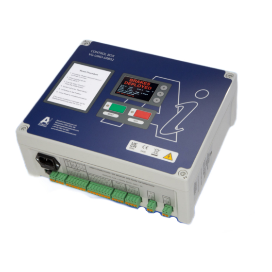
Specific hazards arise for inadequate lighting, untidy work area, trip hazards and poor access. The Control Box (UMD-SRB02) It is recommended that the Control box is ideally mounted at approximately 1.5 metres high on to a solid wall adjacent to the main lift control panel and close to the rope brake and monitoring pulley position. -
Page 12: Wiring
Wiring of power and internal main lift connections must be carried out by a competent electrician, and checked prior to applying power. 12 Atwell International Limited... - Page 13 Wiring (continued) SAFETY NOTE: Once connected to the main lift control panel there will be potentially live connections within the VG UMD-SRB02 enclosure and the terminal housing even when the fuses for the enclosure have been withdrawn. Fitting of fuses & battery connection Note: Fuses are all now fitted at the factory prior to dispatch.
- Page 14 The operation of these switches is essential to enable the VG UMD-SRB02 to operate safely, i.e. If a cable is broken or the lift over speeds the UMD-SRB02 will be FAIL SAFE. i.e. any problems, the rope brakes or safety gear will be deployed.
- Page 15 Do not leave the lift to run in “engineer mode”, this is purely a function to allow you to carry out maintenance on the lift without triggering uncontrolled movement. You will have circumvented the part of the safety circuit. UMD-SRB02 Version 1...
- Page 16 Main Fuse Connection is v 500mA Used By Atwell for external reset RELAY Used By Atwell For future upgraded models - No connection required Used By Atwell for external load monitoring LOAD For future upgraded models - No connection required CELLS...
- Page 17 Volt Free / Dry contact, it will open when there is a fault detected and closes whel all is OK. UMD-SRB02 Version 1...
-
Page 18: Mechanical Installation
Check for smooth operation and no excessive play or run out. Connect the other end of this sensor cable to the UMD-SRB02 panel via the connecting plugs, if you have not done so yet. 18 Atwell International Limited... -
Page 19: Normal Operation
(If there are faults rectify them first.) • 1. Check the visual display on the UMD-SRB02 control panel for the reason of engagement. • 2. Carry out a visual inspection of the VG Rope Brake/s Checking which brake has fully engaged. -
Page 20: Bypassing The System
• Select confirm. • The controller will then remain in By-Pass for 1 hour only and then return to normal running. To get back to normal running mode. • Select Menu. • Mode Select. • Run. 20 Atwell International Limited... -
Page 21: Test Deployment Of Brakes
Select static test: You then have 30 seconds to deploy the brakes or Safety gear. • Screen will show deployed. TO RESET • Press Green reset button. • Select confirm. • Manually reset brakes or safety gear. • Press Green reset button. • Screen will show reset. UMD-SRB02 Version 1... -
Page 22: Uncontrolled Movement Settings
The lift should be parked at a landing floor with both the landing and car doors open. Ensure the VG UMD-SRB02 control box is monitoring the lift doors (Red). Description of levelling & re-leveling 0.8m/sec 0.30m/sec Fix the hand winding wheel to the machine and slowly hand wind the lift until the rope brake is triggered and the drop jaw has engaged the ropes. -
Page 23: Instructions For Rescue Operations
1. Ensure both rope brakes are reset and the corresponding green lights are lit on the control panel. 2. Ensure the reason for the engagement has been fully investigated and resolved 3. Check the lift is operating correctly. UMD-SRB02 Version 1... -
Page 24: Regular Maintenance
If there is any doubt then you should render the lift out of service and contact Atwell International or one of its appointed agents for assistance. -
Page 25: Maintenance Instructions
If during the routine visits it is apparent that there are any signs of damage or wear or abuse to any of the components of the system, then you must remove the lift from service until the faults are remedied and the installation is tested by a competent person. UMD-SRB02 Version 1... -
Page 26: Spare Parts
230V +/-10% Number of Phases Single Phase, Neutral and Earth Frequency 50 / 60 Hz Full Load Current 2.0 A Normal Running Current 0.5 A Type Of Safety Component Bi-Directional Rope Brake or VG Safety Gears 26 Atwell International Limited... -
Page 27: Definitions
Components which are defined as safety components in either the EU Lifts Directive (2014/33/EU) or the UK Lift Regulations (2016). Competent Maintenance Person Persons with the knowledge, technical ability and equipment able to perform the tasks allocated to them without danger. UMD-SRB02 Version 1... -
Page 28: Very Important
If any attempt is made it will be logged and your warranty and any responsibility placed upon Atwell International will be immediately removed from ALL sites under your control, there will be no exceptions. - Page 29 UMD-SRB02 Version 1...
Need help?
Do you have a question about the UMD-SRB02 and is the answer not in the manual?
Questions and answers