Furman VU-40 - Stereo System Monitor Instruction Manual
- Instruction sheet (2 pages)
Advertisement
Introduction
Congratulations on your purchase of a Furman Sound Model VU-40 Stereo System Monitor. The VU-40 is a convenient rackmount dual channel level monitor for use in sound reinforcement, concert sound, recording studio monitoring, or in any application where a quick visual check of system performance is desirable.
VU-40 Features
- Two independent metering channels
- On/off transient muting function protects speakers
- Familiar VU meter scales
- Green/Yellow/Red LED color coding
- Peak or Average response switch
- Line LeveVPower Out switch for each channel
- Line Level may be set to -10, 0, or +4 dBu
- Sixteen Power Out choices from 20 to 1260 Watts
- Ground lift, on/off switches
Operation
Front Panel
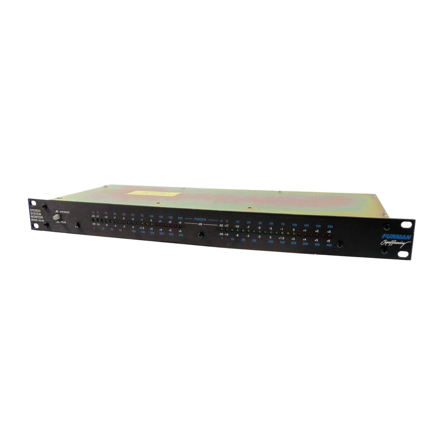
The VU-40 is comprised of two 20 LED bar-graph meters, calibrated in dB like standard VU meters. They may be set with the pushbutton switch on the left side of the front panel to read either Peak (button in) or Average (button out) response. The two meter scales above the LED's are used for Average, while the two scales below are for Peak. Because audio signals are AC (alternating current), their actual voltage level varies from millisecond to millisecond. "Average" refers to the average magnitude during a time span of about 1/4 second. To approximate the action of a traditional electromechanical VU meter, choose the Average setting. Average also gives a good indication of the perceived loudness ot the signal. The Peak setting indicates the highest point of the waveform, regardless of the average. Therefore, the Peak position will always result in higher readings, but it will give a truer indication of how close the signal is to clipping.
Rear Panel
The Input Select switches on the rear-panel select either Line (line level) or Amplifier (power output), allowing you to monitor either the inputs or outputs, respectively, of a power amp. Since each channel may be switched independently, another possibility is to use one VU-40 channel for input and the other for output. Of course, the Line setting may be used to monitor any line level signal, even if no power amp is involved. For Line, the "zero" meter positions may be set to either -10, 0, or +4 dBu with the Line Input slide switch. This switch controls both the left and right channels (assuming both are set to the Line position with their Input Select switches). For line level metering, refer to the white scales on the front panel, which are calibrated in decibels. The choice of -10, 0, or +4 depends on the nominal line level of the other equipment in your system, especially the mixer and tape recorder. If in doubt, consult the manuals for that equipment.
When either or both of the Input Select switches are set to Amplifier, the VU-40 is ready to monitor the output(s) of a power amp. The blue scales, calibrated in percent of full power, are used. There are 16 power output choices from 20 to 630 watts for 8 ohm loads, or trom 40 to 1260 watts for 4 ohm loads. Check the maximum power output for your amplifier and the rated impedance og your speakers to determine which range to use. The exact wattage corresponding to 100 percent is determined by the settings of the tour Amplifier Power switches, according to the following table. The switches are shown as seen at the rear panel, from left (closest to Power Amp binding posts) to right.
Amplifier Power Switches
| When switches are set as follows: | The 100% reading in watts is | ||||
| Left | Right | 8 ohms | 4 ohms | ||
| down | down | down | down | 20 | 40 |
| up | down | down | down | 25 | 50 |
| down | up | down | down | 32 | 64 |
| up | up | down | down | 40 | 80 |
| down | down | up | down | 50 | 100 |
| up | down | up | down | 63 | 126 |
| down | up | up | down | 80 | 160 |
| up | up | up | down | 100 | 200 |
| down | down | down | up | 125 | 250 |
| up | down | down | up | 160 | 32O |
| down | up | down | up | 20O | 400 |
| up | up | down | up | 250 | 500 |
| down | down | up | up | 320 | 640 |
| up | down | up | up | 400 | 800 |
| down | up | up | up | 500 | 1000 |
| up | up | up | up | 630 | 1260 |
In adjusting system levels, the VU-40's meters serve as a guide to avoid overdriving the power amplifier, which can result in cipping distortion. The arnplifier's output should only rarely be alIowed to exceed 100% of its rated power. The rneter LED's are color coded red above 100% so you can see overtoads at a glance. When only green lights show, the arnp is operating in a safe range. In between, there are three yellow lights warning that the signal level is cease to overdriving.
Transient Muting
A special VU-40 feature is turn-on/turn-off transient muting. To use it, tine level feeds to the power arnp are routed first to the VU-40, then back out to the power amp. When AC power is applied or rernoved, the power amp feed will be rnuted for one second, eliminating loud thurnps with their potential for speaker damage. With a VU-40 channel assigned in this fashion to each power amp in a systern, the entire systern may be switched on and off with one master switch, providing an extra degree of protection for systems operated by inexperienced personnel.
lnstallation
The VU-40's connectors include both a 1/4 inch phone jack and an RCA jack for Line Level input and output for each channel. lf the VU-40 is to be used only for line level monitoring, only the input jacks need be used. However, since this might necessitate splitting the signal to be monitored with a Y-cord or similar device, you may find it more convenient to use the VU-40's output jacks as well, routing the signal in and then back out. This method also provides the benefit of the transient muting feature. lf desired, both the phone and the RCA output jacks can be used simultaneously. This can be useful for signal splitting, if, for instance, you want to route the signal to more than one power amp. However, only one of the two input jacks on each channel should be used as an input (the two jacks are connected together, so the other jack can be used as an output, but it will not have the one second mute). For best results, all cables carrying line level signals should be shielded.
For Power monitoring, a pair of banana jac/ binding post terminals are provided for each channel. The banana terminals are balanced, floating, and isolated, so that the VU-40 can be safely connected to any power amp output without regard for polarity. These cables do not need to be shielded.

To avoid damage to the VU-40, do not connect a power amp output to any phone or RCA jack. Power amp outputs or speakers must connect only to the binding posfs labeled "Power Amplifier."
It is possible to use the VU-40 for Power monitoring and still use the transient muting feature. Simply connect the power amp outputs to the banana jacks, set the lnput Select switches to Amplifier, and route the line level signal at the point to be muted (generally just before the power amp or crossover, if used) into and out of the phone or RCA jacks.
The VU-40 is intended for mounting in standard 19" equipment racks. A logical spot to install it would be just above the amp whose output it is monitoring. Standard racks come equipped with mounting rails with holes tapped for 10-32 machine screws. Be sure to use only 10-32 screws (in pailicular, avoid 10-24 screws, which will fit if forced but will strip the threads). To avoid marring the panel when tightening the screws, use nylon washers under the screw heads.
Ground Lift Switch
In many installations, hum-causing ground loops are formed by the common connection of various pieces of equipment to the power line ground, and by contact between chassis, as in a rack with metal rails. Sliding the ground lift switch up completely isolates all signal grounds from the chassis, breaking any ground loops. The chassis always remains connected to the ground pin on the AC cord for safety and to provide shielding against RF interference.
Balanced Option
lf the balanced option has been installed (Model VU-408)' XLR connectors will be present on each channel for both inputs and outputs. Balanced lines offer the benefits of cancellation of hum, noise, and RF interference which may be picked up in the interconnecting cables. For balanced connections, shielded twisted pair cable must be used. lf desired, the XLR (balanced) and phone (unbalanced) outputs may be used simultaneously. However, only one of the two inputs should be used.
Service
Before returning any equipment for repair, please be sure that it is adequately packed and cushioned against damage in shipment, and that it is insured. We suggest that you save the original packaging and use it to ship the product for servicing. Also, please enclose a note giving your name, address, phone number and a description of the problem.
 NOTE: All equipment being returned for repair must have a Return Authorization (R/A) Number. To get an R/A Number, pfease call the Furman Service Department, (415) 927-1225, between 8 am and 5 pm U.S. Pacific Time. Please display your R/A Number prominently on the front of all packages.
VU-40 SPECIFICATIONS
| LINE IN/OUT | Input lmpedance: Sensitivity for 0 VU: | Greater than 200K ohms. -10 dBu (.245 Vrms) or 0 dBu (.775 Vrms) or +4 dBu (1.23 Vrms) |
| Turn-on Delay: Max. Through Level: Connectors: | Approximately 1 Sec +22 dBu (10 Vrms) VU-40: 1/4" phone and RCA VU-40B: Phone, RCA, and XLR | |
| POWER AMP INPUTS | Input lmpedance: Sensitivity for 0 VU: | Greater than 200K ohms. 16 switch selectable calibrated sensitivities for either 20 to 630 Wafts at 8 ohms, or 40 to 1260 W at 4 ohms |
| Connectors: | Banana binding Post. | |
| METERS | Accuracy: | +0.5 dB (factory set internal trim pot). |

Documents / ResourcesDownload manual
Here you can download full pdf version of manual, it may contain additional safety instructions, warranty information, FCC rules, etc.
Download Furman VU-40 - Stereo System Monitor Instruction Manual
Advertisement

Need help?
Do you have a question about the VU-40 and is the answer not in the manual?
Questions and answers