Table of Contents
Advertisement
Quick Links
This manual serves the following
ComNet Model Numbers:
NW8
NW8E
INSTALLATION AND OPERATION MANUAL
INDUSTRIAL OUTDOOR 802.11A/B/G/N DUAL RADIO
WIRELESS ETHERNET
Thank you for purchasing NetWave® from ComNet. This installation guide applies to
the following models:
NW8: Industrial Multipoint, FCC Version, User Configurable
NW8E: Industrial Multipoint, ETSI Version, User Configurable
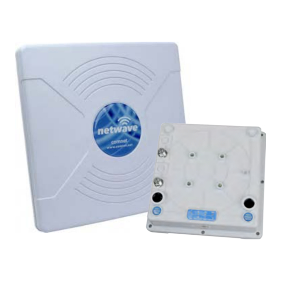
The NetWave® industrially hardened wireless dual radio Ethernet transmission
device is designed to be used with an external antenna and is used for redundant
ring and drop & repeat topologies. Both radios can be configured through the
embedded User Interface as a Client or as an Access Point. Radio 2 supports 5GHz
operation and is connected to the 19dBi internal antenna. Radio 1 is user selectable
for 5GHz or 2.4GHz and connects to an external antenna. The NW8 and NW8E
support up to 145Mbps throughput using MIMO technology. The units can be
powered by an IEEE 802.3af/at PoE compliant device or through a supplied power
injection module with the second Ethernet port operational as an IEEE802.3at PoE
power source. The NW8 is FCC certified for use in North America and the NW8E is
ETSI, DFS and TPC certified for use in the European Union.
Advertisement
Table of Contents

Summary of Contents for NetWave NW8
- Page 1 IEEE 802.3af/at PoE compliant device or through a supplied power injection module with the second Ethernet port operational as an IEEE802.3at PoE power source. The NW8 is FCC certified for use in North America and the NW8E is ETSI, DFS and TPC certified for use in the European Union.
-
Page 2: About This Guide
» Electrical regulations and guidelines » Knowledge of Local Area Network technology Related Documentation The following documentation is also available: » NW8/NW8E Datasheets » NW8/NW8E Quick Start Guides Website For information on ComNet’s entire product line, please visit the ComNet website at http://www.comnet.net Support For any questions or technical assistance, please contact your sales person (sales@comnet.net) or... -
Page 3: Table Of Contents
6.2 NW8 and NW8E Antenna Installation 6.3 NW8 and NW8E Indicating LED Details 6.4 NW8 and NW8E Outdoor Standard Mounting Hardware 14 6.5 NW8 and NW8E Outdoor Upgrade Mounting Hardware 15 6.6 Optional Outdoor Industrial Rated Shielded CAT6 Cable 15 7.0 Key Default Configurations... -
Page 4: Overview
INSTALLATION AND OPERATION MANUAL NW8/NW8E Overview Legal Information No part of this document may be reproduced or transmitted in any form or by any means, electronic and mechanical, for any purpose, without the express written permission of ComNet. Copyright Copyright © 2013 ComNet. All rights reserved. -
Page 5: Introduction
Ethernet port operational as an IEEE 802.3at PoE power source. The NW8 is FCC certified for use in North America and the NW8E is ETSI, DFS and TPC certified for use in the European Union. This manual contains detailed information covering ComNet NetWave outdoor NW8 and NW8E wireless products. -
Page 6: Drop And Repeat - Nw8 And Nw8E
NW8/NW8E 2.0 Drop and Repeat – NW8 and NW8E The Dual Radio Netwave product with external antenna can be used in a Drop and Repeat topology with any other Netwave Access Point. This design is recommended in situations where there is an object blocking Line of Sight. There is a MAC address lock feature for the FCC version that can be enabled for either radio through the user interface but is not enabled by default. -
Page 7: Redundant Ring - Nw8 And Nw8E
INSTALLATION AND OPERATION MANUAL NW8/NW8E 3.0 Redundant Ring – NW8 and NW8E A redundant ring topology is a unidirectional transmission link between devices that forms a closed loop. In this setup, Spanning Tree must be enabled (off by default) to prevent a loop in the network. -
Page 8: Poe Pass-Through Port - Nw8 And Nw8E
NW8/NW8E 4.0 PoE Pass-through Port – NW8 and NW8E The Netwave NW8 and NW8E come with dual Gigabit Ethernet ports. Port 1 supports IEEE 802.3af/at PD PoE power and Port 2 is a Power over Ethernet IEEE 802.3at PSE (Power Sourcing Equipment) port that acts as a voltage source and supplies PoE PD devices with power via the Ethernet cable. -
Page 9: Cabling Requirements
PoE AC ground. Industrial grade shielded Ethernet cable is recommended to help prevent ESD damage commonly experienced with outdoor installations. www.comnet.net/comnet-products/cables Visit The NW8 and NW8E have two N Female external connectors for connecting an antenna. N Female Antenna Connector N Female Antenna... -
Page 10: Hardware Installation
NW8/NW8E 6.0 Hardware Installation 6.1 NW8 and NW8E Outdoor Ethernet Gland Installation There will be two cable glands and a weather seal cap included with each outdoor enclosure. The provided weather seal cap should be used when Port 2 is not in use to prevent damage to the port and the wireless device. - Page 11 INSTALLATION AND OPERATION MANUAL NW8/NW8E Once the gland is tight in the housing, tighten the outer nut/cap making sure the rubber seal squeezes and seals the Ethernet cable to the gland as shown below. Connect one end of an RJ-45 Ethernet cable to the LAN OUT port of the Power Injection Module (PIM) and the other end to LAN of the access point –...
-
Page 12: Nw8 And Nw8E Antenna Installation
NW8/NW8E 6.2 NW8 and NW8E Antenna Installation To connect an external antenna to the NW8 and NW8E, attach RF Cables (not included) to the N Female connectors on the device. RF Cables need to be properly fastened to have a secure connection. Press down firmly on the N Male connector of the antenna cable and tighten. -
Page 13: Nw8 And Nw8E Indicating Led Details
INSTALLATION AND OPERATION MANUAL NW8/NW8E 6.3 NW8 and NW8E Indicating LED Details Note: External RSSI LEDs are for Radio 1 only. One needs to logon to the embedded configuration pages to view the RSSI levels of Radio 2 VISUAL CUE... -
Page 14: Nw8 And Nw8E Outdoor Standard Mounting Hardware
INSTALLATION AND OPERATION MANUAL NW8/NW8E 6.4 NW8 and NW8E Outdoor Standard Mounting Hardware This mounting hardware will support pole diameters up to 3 in (7.6 cm). Below are the parts contained in the standard mounting hardware Here is the mounting hardware assembled shown in a +45° and -45°vertical position TECH SUPPORT: 1.888.678.9427... -
Page 15: Nw8 And Nw8E Outdoor Upgrade Mounting Hardware
INSTALLATION AND OPERATION MANUAL NW8/NW8E 6.5 NW8 and NW8E Outdoor Upgrade Mounting Hardware An upgrade to the outdoor mounting hardware is available. This optional version is of heavier construction supporting an articulating joint and is designed for wall or pole mount supporting up to a 3 inch or 76 mm pole. -
Page 16: Key Default Configurations
INSTALLATION AND OPERATION MANUAL NW8/NW8E 7.0 Key Default Configurations IP Address of Web Server 192.168.10.102 LAN Mode for Web Server Static Addressing Web Server User ID admin Web Server Password admin Web Server Guest User ID guest Web Server Guest Password guest... -
Page 17: Quick Configuration
• Select Apply Settings • Select Save Note: : NW8 and NW8E nodes may need to have the Wireless Mode set to either AP or Client (default is Client for Radio 1 and Access Point for Radio 2). The unit IP addresses will need to be all set to different addresses (default address is 192.168.10.102). -
Page 18: Status Page - Access Point
INSTALLATION AND OPERATION MANUAL NW8/NW8E 9.0 Detailed Configuration 9.1 STATUS Page – Access Point 9.1.1 STATUS_AP Page MAIN Section This section will list the unit uptime as well as the system time which can be set on the SYSTEM TOOLS page. - Page 19 INSTALLATION AND OPERATION MANUAL NW8/NW8E 9.1.3 STATUS_AP Page RADIO 1 Section Wireless Mode Shows the operational mode for the radio. This can be set on the WIRELESS SETTINGS page. Local AP SSID SSID that this AP is broadcasting. Frequency Frequency that the AP is operating on...
- Page 20 INSTALLATION AND OPERATION MANUAL NW8/NW8E 9.1.5 STATUS_AP Page LOCAL AP ERRORS Section RX Invalid NWID Shows the number of SSIDs detected that is different from the Remote AP SSID. This number will continually count up and will count up faster in congested RF environments.
-
Page 21: Status- Radio 2 - Client
INSTALLATION AND OPERATION MANUAL NW8/NW8E 9.2 STATUS- Radio 2 - Client 9.2.1 STATUS-Client Page MAIN Section This section will list the unit uptime as well as the system time which can be set on the SYSTEM TOOLS page. 9.2.2 STATUS-Client Page LAN SETTING Section... - Page 22 INSTALLATION AND OPERATION MANUAL NW8/NW8E 9.2.3 STATUS-Client Page RADIO Section Wireless Mode Lists the operational mode for the radio. This can be set on the WIRELESS SETTINGS page. Remote AP SSID SSID for that the client will scan and connect to.
- Page 23 INSTALLATION AND OPERATION MANUAL NW8/NW8E 9.2.4 STATUS-Client Page LOCAL STATION STATICS Section Received Shows Bytes, Packets, and Errors received Transmitted Shows Bytes, Packets, and Errors transmitted 9.2.5 STATUS-Client Page LOCAL STATION ERROR Section RX Invalid NWID Shows the number of SSIDs detected that is different from the Remote AP SSID.
-
Page 24: Wireless Settings Page Radio 1 - Access Point
INSTALLATION AND OPERATION MANUAL NW8/NW8E 9.3 WIRELESS SETTINGS Page Radio 1 – Access Point TECH SUPPORT: 1.888.678.9427 INS_NW8[E]_REV– 06/10/13 PAGE 24... - Page 25 INSTALLATION AND OPERATION MANUAL NW8/NW8E 9.3.1 WIRELESS SETTINGS - AP Page BASIC WIRELESS SETTINGS Section Note: Any settings changes made on this page will require the hitting Apply Settings button then Select Save. Wireless Mode The user can select either Access Point or Client mode of operation.
- Page 26 INSTALLATION AND OPERATION MANUAL NW8/NW8E Interference When pressed, will generate a pop up window showing all the Analyzer Button detected AP signals like the image below: Transmit Power This section will set the RF transmit power. The maximum RF power available will be limited in software based on the gain of the integrated antenna and the region the unit was programmed to operate in.
- Page 27 INSTALLATION AND OPERATION MANUAL NW8/NW8E Pre-shared Key (For use with WPA security) Here an alpha-numeric between 8 and 63 character long pre-shared key can be entered. Identity (For use with 802.1x security) identification credential and be entered here to be used by the WPA supplicant for EAP authentication.
- Page 28 INSTALLATION AND OPERATION MANUAL NW8/NW8E 9.3.4 WIRELESS SETTINGS - AP Page RSSI LED INDICATOR Section This section allows the user to set the LED threshold for the RSSI Indicating LEDs. Note: LED1 on this page is not brought out on the external LED label, LED2 corresponds to Ethernet/RSSI2 on the LED label, LED3 corresponds to RSSI3, and LED4 corresponds to Status/RSSI4.
-
Page 29: Wireless Settings - Radio 1 Client Page
INSTALLATION AND OPERATION MANUAL NW8/NW8E 9.4 WIRELESS SETTINGS - Radio 1 Client Page TECH SUPPORT: 1.888.678.9427 INS_NW8[E]_REV– 06/10/13 PAGE 29... - Page 30 INSTALLATION AND OPERATION MANUAL NW8/NW8E 9.4.1 WIRELESS SETTINGS - Radio 1 Client Page BASIC WIRELESS SETTINGS Section Note: Any settings changes made on this page will require selecting the ‘Save’ pop up button then the ‘Apply Settings’ button. Wireless Mode The user can select either Access Point or Client mode of operation.
- Page 31 INSTALLATION AND OPERATION MANUAL NW8/NW8E 9.4.2 WIRELESS SETTINGS - Radio 1 Client Page WIRELESS SECURITY Section Security Here the end user can select the wireless security mode. Options available are None, WEP, WPA, WPA2, and 802.1x port-based security. 802.1x is for secure user-based authentication through a centralized authentication server.
- Page 32 INSTALLATION AND OPERATION MANUAL NW8/NW8E 9.4.3 WIRELESS SETTINGS - Radio 1 Client Page LONG RANGE PARAMETERS Section Long Range Check box to enable long range parameters. This is enabled and set Parameters to 1000m by default. 1000m should meet a majority of the system link distances but if the link distance goes beyond 1000m, this section will need to be adjusted on both ends of the link –...
-
Page 33: Wireless Settings - Radio 2 Client Page
INSTALLATION AND OPERATION MANUAL NW8/NW8E 9.5 WIRELESS SETTINGS – Radio 2 Client Page TECH SUPPORT: 1.888.678.9427 INS_NW8[E]_REV– 06/10/13 PAGE 33... - Page 34 INSTALLATION AND OPERATION MANUAL NW8/NW8E 9.5.1 WIRELESS SETTINGS - Radio 2 Client Page BASIC WIRELESS SETTINGS Section Note: Any settings changes made on this page will require selecting the ‘Save’ pop up button then the ‘Apply Settings’ button. Wireless Mode The user can select either Access Point or Client mode of operation.
- Page 35 INSTALLATION AND OPERATION MANUAL NW8/NW8E 9.5.2 WIRELESS SETTINGS - Radio 2 Client Page WIRELESS SECURITY Section Security Here the end user can select the wireless security mode. Options available are None, WEP, WPA, WPA2, and 802.1x port-based security. 802.1x is for secure user-based authentication through a centralized authentication server.
- Page 36 INSTALLATION AND OPERATION MANUAL NW8/NW8E 9.5.3 WIRELESS SETTINGS - Radio 2 Client Page LONG RANGE PARAMETERS Section Long Range Check box to enable long range parameters. This is enabled and set Parameters to 1000m by default. 1000m should meet a majority of the system link distances but if the link distance goes beyond 1000m, this section will need to be adjusted on both ends of the link –...
- Page 37 INSTALLATION AND OPERATION MANUAL NW8/NW8E 9.5.5 WIRELESS SETTINGS - Radio 2 Client Page NW8E (ETSI Version) Only Note: The ETSI version of the NetWave NW8E has the added feature of being able to enable or disable Radio 2 Enable Radio 2 Enable or Disable Radio 2 Remember to select Apply Settings if any changes were made.
-
Page 38: Wireless Settings Page Radio 2 - Access Point
INSTALLATION AND OPERATION MANUAL NW8/NW8E 9.6 WIRELESS SETTINGS Page Radio 2 – Access Point TECH SUPPORT: 1.888.678.9427 INS_NW8[E]_REV– 06/10/13 PAGE 38... - Page 39 INSTALLATION AND OPERATION MANUAL NW8/NW8E 9.6.1 WIRELESS SETTINGS - Radio 2 AP Page BASIC WIRELESS SETTINGS Section Note: Any settings changes made on this page will require the hitting Apply Settings button then Select Save. Wireless Mode The user can select either Access Point or Client mode of operation.
- Page 40 INSTALLATION AND OPERATION MANUAL NW8/NW8E Interference When pressed, will generate a pop up window showing all the Analyzer Button detected AP signals like the image below: Transmit Power This section will set the RF transmit power. The maximum RF power available will be limited in software based on the gain of the integrated antenna and the region the unit was programmed to operate in.
- Page 41 INSTALLATION AND OPERATION MANUAL NW8/NW8E Pre-shared Key (For use with WPA security) Here an alpha-numeric between 8 and 63 character long pre-shared key can be entered. Identity (For use with 802.1x security) identification credential and be entered here to be used by the WPA supplicant for EAP authentication.
- Page 42 Remember to select Apply Settings if any changes were made. 9.6.5 WIRELESS SETTINGS - RADIO 2 AP Page ETSI Version Only Note: The ETSI version of the NetWave NW8E has the added feature of being able to enable or disable Radio 2...
-
Page 43: Network Settings Page - Client Or Access Point
INSTALLATION AND OPERATION MANUAL NW8/NW8E 9.7 NETWORK SETTINGS Page – Client or Access Point 9.7.1 NETWORK SETTINGS Page LOCAL AREA NETWORK Section LAN Mode Embedded web server addressing mode. Options are static or dynamic for an address from a local DHCP server. - Page 44 INSTALLATION AND OPERATION MANUAL NW8/NW8E DHCP Stop IP DHCP address block stop address Address DHCP Netmask DHCP Network mask that the DHCP sever will pass to the DHCP clients DHCP Gateway IP IP address for the network segment gateway that the DHCP sever will...
-
Page 45: System Tools Page - Client And Access Point
INSTALLATION AND OPERATION MANUAL NW8/NW8E 9.8 SYSTEM TOOLS Page – Client and Access Point TECH SUPPORT: 1.888.678.9427 INS_NW8[E]_REV– 06/10/13 PAGE 45... - Page 46 INSTALLATION AND OPERATION MANUAL NW8/NW8E 9.8.1 SYSTEM TOOLS Page STP Section Enable STP Not enabled by default Root Priority Allows the user to set priorities in each node used during the root bridge selection process. Root Hello Timer For setting STP hello times. Default is 2 Root Forward For setting STP forward delay.
- Page 47 INSTALLATION AND OPERATION MANUAL NW8/NW8E 9.8.4 SYSTEM TOOLS Page SNMP SETUP Section Enable SNMP Not enabled by default Read Password Password to query the device Engine ID Engine ID for the SNMP agent. Default is 800007e5BD00002704D000007c Enable SNMP trap Not enabled by default.
- Page 48 INSTALLATION AND OPERATION MANUAL NW8/NW8E 9.8.8 SYSTEM TOOLS Page MORE TOOLS Dropdown menu A More Tools pull down menu is present in the top right hand section of the SYSTEM TOOLs page as shown below: Ping Utility Use this utility to test network connections using ICMP ping.
- Page 49 INSTALLATION AND OPERATION MANUAL NW8/NW8E Bridge Table This table displays a list of devices connected to the node bridge interface as shown below DHCP Active Leases This table displays a list of active DHCP leases if this node were configured as a DHCP server.
-
Page 50: Admin Page - Client Or Access Point
INSTALLATION AND OPERATION MANUAL NW8/NW8E 9.9 ADMIN Page – Client or Access Point TECH SUPPORT: 1.888.678.9427 INS_NW8[E]_REV– 06/10/13 PAGE 50... - Page 51 INSTALLATION AND OPERATION MANUAL NW8/NW8E 9.9.1 ADMIN Page FIRMWARE UPGRADE Section Firmware Version: Displays the version currently running Firmware Upgrade procedure: • Press the browse button to browse to a location where the upgrade image is located • Once the file has been located hit the Upload button. You should see the following screen while the image is uploading: •...
- Page 52 INSTALLATION AND OPERATION MANUAL NW8/NW8E • Press the upgrade button and you should see a prompt confirming the upgrade to continue. Select Yes: • The following screen will now show reminding the user to not reboot during an upgrade process. This screen should render for at least 60 seconds if the PC browsing to this particular node is locally connected.
- Page 53 INSTALLATION AND OPERATION MANUAL NW8/NW8E • The last screen will confirm to reboot. Hit Yes. • Unit will reboot and the page will refresh after about 60 seconds. • It is recommended that a factory reset be performed by hitting the Restore to Default button at the bottom of the ADMIN page but may not be required.
- Page 54 INSTALLATION AND OPERATION MANUAL NW8/NW8E 9.9.5 ADMIN Page CONFIG MANAGEMENT Section This section allows the user to save the current configuration of the node in a file allowing backup of node configuration. Backup When the Backup button is presses, a prompt will pop up asking Configuration where to store the configuration file.
-
Page 55: Agency Compliance
INSTALLATION AND OPERATION MANUAL NW8/NW8E 10.0 Agency Compliance Changes or modifications not expressly approved by the party responsible for compliance could void the user’s authority to operate the equipment. This device complies with Part 15 of the FCC Rules. Operation is subject to the following two conditions: •... - Page 56 INSTALLATION AND OPERATION MANUAL NW8/NW8E RF Exposure Warning The antennas used for this transmitter must be installed to provide a separation distance of at least 2.52m from all persons and must not be located or operating in conjunction with any other antenna or transmitter.
-
Page 57: Gpl (General Public License) Statement
Such products include NetWave series of products. As part of these products, ComNet may have distributed to you hardware and/or software that contained a version of free software programs developed by the Free Software Foundation, a separate not-for-profit organization without any affiliation to ComNet. - Page 58 INSTALLATION AND OPERATION MANUAL NW8/NW8E TECH SUPPORT: 1.888.678.9427 INS_NW8[E]_REV– 06/10/13 PAGE 58...
- Page 59 INSTALLATION AND OPERATION MANUAL NW8/NW8E ComNet Customer Service Customer Care is ComNet Technology’s global service center, where our professional staff is ready to answer your questions at any time. Email ComNet Global Service Center: customercare@comnet.net Contact Information ComNet – www.comnet.net...
Need help?
Do you have a question about the NW8 and is the answer not in the manual?
Questions and answers