Table of Contents
Advertisement
Quick Links
Advertisement
Table of Contents

Summary of Contents for Lincoln Electric CHD1000
- Page 1 High-vacuum units HIGH-VACUUM UNITS CHD1000 - 2000 - 3000 - 4000 SAFETY INSTRUCTIONS FOR USE AND MAINTENANCE N° EM61000120 - EM61000121 - EM61000122 - EM61000123 - EM61000124 8695 8421 EDITION : EN Instructions for use REF : REVISION : A...
- Page 2 Thank for the trust you have expressed by purchasing this equipment, which will give you full satisfaction if you follow its instructions for use and maintenance. Its design, component specifications and workmanship comply with applicable European directives. Please refer to the enclosed CE declaration to identify the directives applicable to it.
-
Page 3: Table Of Contents
8695 8421 CONTENTS A - INTRODUCTION .......................... 1 USING THE MANUAL ......................1 MACHINE GUARANTEE ......................1 ASSISTANCE ........................... 1 DESCRIPTION OF PICTOGRAMS ..................1 B - GENERAL SAFETY INSTRUCTIONS ..................2 ELECTRICAL SAFETY ......................2 PERSONAL PROTECTION ..................... 3 FILTRATION OF FUMES AND DUST .................. - Page 4 EN ISO 61439-1 : 2011 EN ISO 61439-2 : 2011 Air Treatment Products Manager, authorised to compile the technical manufacturing document M. Patrick DEGROOTE LINCOLN ELECTRIC FRANCE SAS Avenue Franklin Roosevelt 76120 – LE GRAND QUEVILLY Manufacturer LINCOLN ELECTRIC FRANCE SAS Avenue Franklin Roosevelt 76120 –...
-
Page 5: A - Introduction
Before the filter is used by a new user, make sure that they have read this manual and understood all the explanations provided. For any further information, please feel free to contact the technical departments of LINCOLN ELECTRIC. MACHINE GUARANTEE This machine is guaranteed for 12 months from the date of purchase. -
Page 6: B - General Safety Instructions
8695 8421/A B - GENERAL SAFETY INSTRUCTIONS ELECTRICAL SAFETY Connection to the mains Before you connect your machine, please make sure that: — The meter, the overintensity protection system and the electrical installation are compatible with its maximum power rating and its supply voltage. —... -
Page 7: Personal Protection
8695 8421/A PERSONAL PROTECTION Risks of external injury relating to welding operations Whole body — The operator must be clothed and protected to suit the requirements of the job. — Make sure that no part of the bodies of operators and helpers can come in contact with metal pieces or parts that are live or are liable to become live accidentally. - Page 8 8695 8421/A Specific case of chlorine solvents in welding: (used for cleaning or degreasing). — The fumes from these solvents can be changed into toxic gases when subjected to arc radiation, including from a distance. — Such solvents may therefore not be used in locations where electric arcs occur, if the solvents are not in a sealed enclosure.
-
Page 9: Filtration Of Fumes And Dust
— Not obstruct the air outlet of the machine. — Not introduce external elements into the filter (paper, cloths, cigarette butts etc.) — Replace the filter medium with new original LINCOLN ELECTRIC medium, which alone can guarantee the filtration characteristics. -
Page 10: C - Overall Description
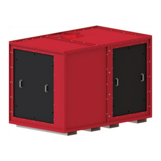
8695 8421/A C - OVERALL DESCRIPTION For your safety and optimum performance, please read this manual carefully before using the filter. DESCRIPTION OF THE EQUIPMENT The sandwich panel on metal structure construction optimises the weight and strength of the unit. It can be put in place easily thanks to its monobloc construction, which helps minimise noise. -
Page 11: D - Technical Description
8695 8421/A D - TECHNICAL DESCRIPTION COMPOSITION OF THE UNIT Filtration compartment Dust drum Fan compartment Components fixed to the unit Power on indicator Main disconnecting switch Emergency stop... -
Page 12: Description Of The Ui Screen: Home Page
8695 8421/A DESCRIPTION OF THE UI SCREEN: HOME PAGE Operating mode: - Manual - Weekly clock - Automatic Settings info (Hz – kW) Previous Next screen screen Fault management COMPOSITION OF THE ELECTRICAL CABINET 400/24 V power supply Circuit breakers Relay Connection terminal block... -
Page 13: Operating Principle
8695 8421/A OPERATING PRINCIPLE Operating principle of the high-vacuum unit Polluted air is taken into the unit through the pre- filter located on the panel on the side of the unit. Filtered air is expelled by the fan and discharged outside. -
Page 14: Fan Of The 1000 M³/H - 25000 Pa
8695 8421/A FAN OF THE 1000 M³/H - 25000 PA Type : Centrifugal fan 22 kW - HPB 725 - 2 - SV75 Operating point: 1000 m³/h with 24000 Pa at 75 Hz FAN OF THE 2000 M³/H - 25000 PA Type : Centrifugal fan 37 kW - HPB 725 - 2 - SV75 Operating point:... -
Page 15: Fan Of The Chd 3000 M³/H - 25000 Pa
8695 8421/A FAN OF THE CHD 3000 M³/H - 25000 PA Type : Centrifugal fan 45 kW - HPB 725 - 2 - SV75 Operating point: 3000 m³/h with 24000 Pa at 75 Hz FAN OF THE CHD 4000 M³/H - 25000 PA Centrifugal fan 55 kW - HPB 725 –... -
Page 16: E - Installing The Unit
8695 8421/A E - INSTALLING THE UNIT MONTAGE The unit is supplied in a single assembly and only needs to be positioned where it is needed, in the workshop or outside the building. The filter can be handled with a lift truck thanks to the fork pockets provided under the frame. - Page 17 8695 8421/A STEP-BY-STEP STARTING OF THE UNIT In order to guarantee easy and complete starting up, here is the order of the different key stages that must be carried out: Electrical connection of the power supply to the 400 V three-phase system. Connection of the remote control with the UI screen.
- Page 18 8695 8421/A 2- Connecting the stack light : The stack light has three lights : White: power to the filter on Green: filter operating Red: variable frequency drive fault 3- Putting the unit into service : Set the main switch (on the side) to 1. The white power indicator will go on.
- Page 19 8695 8421/A VARIABLE DRIVE CONFIGURATION 1- Operating principle : The variable drive is used for one of its most basic functions, namely overspeed operating. Thanks to the types of fan curve used, we can make a fan operate at a speed from 70 to 87 Hz. With conventional starting up, it would not be possible to operate it above 50 Hz (electrical system frequency).
- Page 20 8695 8421/A Configuration based on the settings : 1000m³/h 1000m³/h 2000m³/h 3000m³/h 4000m³/h Versions 20000 Pa 25000 Pa 25000 Pa 25000 Pa 25000 Pa Parameter Description Value Value Value Value Value Input data by integrate FMOD terminal On/Off control by the CMOD terminal block Max.
-
Page 21: Configuration Of The Ui Screen
8695 8421/A CONFIGURATION OF THE UI SCREEN HMI program version (accessible in Maintenance mode) Clock setting Operating mode: Access to modes: - Manual - Administrator - Weekly clock - Maintenance - Automatic - Operator Settings info (Hz – kW) Previous screen Next screen Fault management Clock screen... - Page 22 Press the Reset icon after the operation Access to Systems screen Systems screen Press the logo « Lincoln Electric » After entering the codes, press: - Box to unlock the HMI - The box on the left to go back to the home screen...
- Page 23 8695 8421/A HD damper adjustment screen Settings screen Changes permitted: Fan stopping time Press the Regul HD icon on the screen Compressed air limit opposite to display this screen Factory values: Fan stopping time = 30 sec Compressed air limit = 4500 mbar Operating mode screen Languages screen 3 possible operating modes...
- Page 24 8695 8421/A Error message screen Display of operating error messages Press the logo to erase the faults list Saving on USB stick possible (Insert at the right of the HMI screen) Maintenance alarms screen Out of service screen Orange dot to show maintenance time The DIGIFILTER is out of service: overrun: Possible causes:...
- Page 25 8695 8421/A CONFIGURATION OF REGULATION HD The high-vacuum turbine is cooled by the volume of air passing through the extraction system. When only a few torches are used, the volume of air is not sufficient for cooling the extraction turbine. In that case, the HD regulation must be adjusted appropriately using the branch damper and the system connection.
-
Page 26: F - Maintenance
The performance of operations that may not be carried out or are contrary to the standards and procedures of the “General instructions” section would release LINCOLN ELECTRIC from liability for any damage caused and would void the guarantee if it is still valid. -
Page 27: Fan
BV-4 BV-5 BV-1 10,6 BV-2 ALARM BV-3 11,8 BV-4 BV-5 BV-1 Depending on history Depending on history BV-2 Depending on history Depending on history STOP BV-3 12,5 BV-4 11,2 BV-5 Nota : Lincoln Electric commercialise des ventilateurs de catégorie BV3... - Page 28 8695 8421/A All maintenance operations are to be carried out with the power to the system switched off. The user may not modify the construction of the fan in any way Check that dust is not being deposited in large quantities on: The motor ventilation blades.
- Page 29 8695 8421/A Front lubricator Rear lubricator Bearing maintenance Bearing inspection As soon as the motor shows the following: - noise or abnormal vibrations, - abnormal heating at the bearing when it is lubricated correctly; the condition of the bearings must be inspected. Damaged bearings must be replaced as soon as possible to prevent more significant damage to the motor and driven parts.
-
Page 30: Maintenance Of Filtering Elements
8695 8421/A MAINTENANCE OF FILTERING ELEMENTS PRE-FILTER From time to time (every week at the start) as a preventive measure or whenever extraction no longer seems adequate: Clean with compressed air in a very well ventilated room or by immersion in a solution of water + FILTERCLEAN 20L part no. -
Page 31: Electrical Diagrams
8695 8421/A ELECTRICAL DIAGRAMS... - Page 32 8695 8421/A...
- Page 33 8695 8421/A...
- Page 34 8695 8421/A...
- Page 35 8695 8421/A...
- Page 36 8695 8421/A...
- Page 37 8695 8421/A...
- Page 38 8695 8421/A LIST OF PARTS OF THE ELECTRICAL CABINET Components specific to the unit CHD 1000 – 20000 Pa Description Reference Characteristics Part noLincoln Disconnecting switch 45 A OT63FT3 Please enquire Motor circuit breaker GV3P40 Please enquire Contactor 15 kW – 400 V LC1D40AV7 Please enquire Schneider ATV 212 –...
- Page 39 8695 8421/A Components specific to the unit CHD 4000 – 25000 Pa Part no Description Reference Characteristics Lincoln Disconnecting switch 100 A Eaton Y7 - 20378 Please enquire 3P motor circuit breaker125 A A9N18369 Please enquire Contactor 55 kW – 400 V LC1 D115AV7 Please enquire Schneider ATV 212 –...
- Page 40 8695 8421/A SPARE PARTS ESCRIPTION ART NUMBER UANTITY Metal pre-filter (500 x 500 x 24) mm – Class EU2 W000379647 HCAS 240– 4 – 0.75 kW cooling fan Please enquire Crystal tube Ø10 – L10M EM61000493 Quarter-turn lock EM61000474 Kit of sealing strips + angle seals EM61000475 HD unit damper servo motor EM61000477...
- Page 41 8695 8421/A...
-
Page 42: Personal Notes
8695 8421/A PERSONAL NOTES Lincoln Electric France S.A.S. Avenue Franklin Roosevelt 76120 Le Grand Quevilly 76121 Le Grand Quevilly cedex www.lincolnelectriceurope.com...