Table of Contents
Advertisement
Quick Links
Advertisement
Table of Contents

Related Manuals for Empava EMPV-SPA3550


Summary of Contents for Empava EMPV-SPA3550
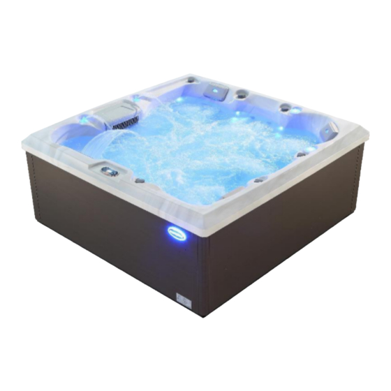
- Page 1 SPA Installation and Directions of Use EMPV-SPA3550...
-
Page 2: Table Of Contents
Content Warnings................................1 I. USA Balboa Control System Instructions ....................2 CNBP501X Tech Sheet.......................... 2 Basic Functions Setup..........................3 Hardware Setup............................4 II. Description on Using Parts .........................14 1. Heater / Thermostat ..........................14 2. Air pump ..............................14 3. Paper element filters daily maintenance ....................14 4. -
Page 3: Warnings
■Warnings: Please read the following instructions before operation and installation, which is a safety guaranty to SPA users. 1. The system must be installed by qualified technicians, switch for electricity leakage should be installed at a place convenient to be controlled or operated. 2. -
Page 4: Usa Balboa Control System Instructions
30. The bearing of the water pumps may get stuck after this SPA hasn’t been used for a long time, so the water pumps may not working when pressing the water-pump buttons on control panel. If the water pump not working because of water bearing get stuck, then you can notice that no water current through jets or no suction- force in the skimmer. -
Page 5: Basic Functions Setup
System Revision History Part # Date Originator Changes Made 56582 4195 01-15-14 BP501G3 initial draft. Adds GFCI Trip (but not GFCI Automatic Test). Updated to latest software version, adding topside-inter- 56583 grated bba™ support. 56584 ZT000148 4467 02-18-15 Customer Spin off custom version of BP501G3 without 2-Speed Pump 2, and adding simplified menus version of eash Setup, and with new default Setup. -
Page 6: Hardware Setup
Hardware Setup Wiring Diagram CNBP501X PN 56849-02 MOVE WIRE TO CONNECT J2O TO J13 FOR BLOWER IN SETUPS 2, 3, 7 & 8 J5 (A1-A4) 11-22-16 CONNECT ONLY TO CIRCUITS PROTECTED BY A CLASS A GFCI. TP (MAIN) PANELS F6 0.3A 250V A DISCONNECTING MEANS MUST BE INSTALLED WITHIN SIGHT FROM J33 or J45 THE EQUIPMENT AND AT LEAST 5 FEET (1.52 M) FROM THE... - Page 7 Changing Software Setups with TP800 / TP900 / spaTouch™ Menued Panel Test Menu Access (S1, Switch 1 ON) Service Technician ONLY. DANGER! HIGH VOLTAGE WILL BE ACCESSIBLE! SERVICE TECHNICIAN ONLY! While the system is running, move DIP Switch 1 (on S1 on the Main circuit board) to ON. The system will enter Test Mode.
- Page 8 Changing Software Setups with TP600 / TP400 Continued Again, You will have 1 minute to complete the setup change after you manually exit Priming Mode. THIS SYSTEM IS Immediately after exiting Priming Mode, press this sequence of buttons: Warm*, Light, Warm, Warm, Warm, Warm. Continue to press Warm until the diplay CONFIGURED AS SETUP # shows the Setup Number (S-01, S-02, etc.) you want to switch to.
- Page 9 DIP Switch Functions Fixed-fuction DIP Switches Test Mode (normally Off). In “ON” position, add one high-speed pump (or blower) with Heater. In “ON” position, add two high-speed pumps (or 1 HS Pump and Blower) with Heater. In “ON” position, enables Special Amperage Rule B. See Special Features section under Configuration Options for functionality with your system. In “OFF”...
- Page 10 Replacement Parts PCBA: Main PCBA: 56851-02 Expander PCBA: 55153 HEATER(s): Plug + Click Heater Kit: 58306 5.5kW 800Inc 58303 4.0kW 800Inc Temp Sensor Kit: 53605 CABLES: 21302 Jumper 120V Heater FUSES: Part Number Amperage Location 30136 F5, F1 (Expander) 20600 F2, F4 21581 3/10A...
- Page 11 BP501 Configuration Options Temperature Features Feature Default Options Increment Temperature Display °F °C, °F All temperatures must be specified in °F. The system converts °F to °C dynamically. If Celsius is required for default settings, choose a desired °C value that (after rounding) cor- responds to a Fahrenheit value.
- Page 12 BP501 Configuration Options Reminder Features Feature Default Options Increment Reminders Shown* Yes, No Check pH 7 Days See Reminder Period Note 1 Days Check Sanitizer 7 Days See Reminder Period Note 1 Days Clean Filter 7 Days See Reminder Period Note 1 Days Test GFCI 60 Days...
- Page 13 TP800 Panel Configuration Button Layout Table Feature Setup 1 Setup 2 Setup 3 Setups 4 & 11 Setup 5 Jets 1 Jets 1 Jets 1 Jets 1 Jets 1 Jets 2 Jets 2 Blower Jets 2 Light 1 Jets 3 Blower Light 1 Light 1...
- Page 14 TP600 Panel Configuration Button Layout Table Button Setups 1 & 6 Setups 2 & 7 Setups 3 & 8 Setups 4, 9, 11 Setups 5 & 10 & 12 Jets 1 Jets 1 Jets 1 Jets 1 Jets 1 Jets 2 Jets 2 Blower Jets 2...
- Page 15 BP501 Configuration Options Auxilliary Panel Features on Bank 1* Feature Default Aux Button A1 Jets 1 Aux Button A2 Jets 2 Aux Button A3 Jets 3 in Setups 1 & 6 Blower in Setups 2, 3, 7 & 8 Undefined in Setups 4, 5, 9 & 10 Aux Button A4 Light *Bank 1 consists of J5 on the Main Circuit Board.
-
Page 16: Description On Using Parts
II. Description on Using Parts 1. Heater/Thermostat 1) Normal starting up time is 4-8 hours 2) SPA Thermostat cannot be heated by man in the air, or there will be danger. If there is something wrong in operation, professional servant is a must to prevent the risk of electricity leakage. 2. -
Page 17: Change And Instruction Of The Selective Fragrance Box Pieces
4) Change the core paper filter half a year once, depends on the high quality of water, lifetime of paper filter can be properly extended. 5) Change a new paper filter, take out a new one and tear out the package of the paper core and put it inside the filtration bucket. -
Page 18: Ⅴ. Instructions On Maintenance
4) Remove the water-return unit and nozzle for cleaning and removing dirt. 5) Do not frequently wipe the gold and chrome plated parts (do not contact it with organic solvent). 6) Please keep blunt and knife away from the surface, and butt or the things over 60 degree should be away from that too. - Page 19 NOTICE: The usage manual is only for reference, and all data subject to the actual product, any update without notice. EMPAVA APPLIANCES INC. 15253 DON JULIAN RD CITY OF INDUSTRY,CA 91745 TEL:888-682-8882 WWW.EMPAVA.COM...
Need help?
Do you have a question about the EMPV-SPA3550 and is the answer not in the manual?
Questions and answers