
Summary of Contents for KUKJE MACHINERY A1000
- Page 1 ENGINE SERVICE MANUAL Engines: A1000 - Branson 2200 A1100 - Branson 2500 A1100T - Branson 2900...
- Page 2 Small Engine 1. ENGINE APPEARANCE, SPECIFICATION AND NAMES OF PARTS 1.1. ENGINE APPEARANCE 1.1.1. Natural Aspirated E/G and Turbo engine KUKJE RGO 60...
- Page 3 RGO 60 1.1.2. TURBO CHARGER ENGINE 1.2. Engine specification 1.2.1. Small engines Engine MODEL 단위/Unit A1000 A1100 A1100T Type Vertical Water-Cooled 4Cycle Diesel Engine No. of Cylinders Bore×Stroke 74×82 78×82 78×82 Displacement 1,056 1,175 1,175 Combustion System Swirl chamber system...
-
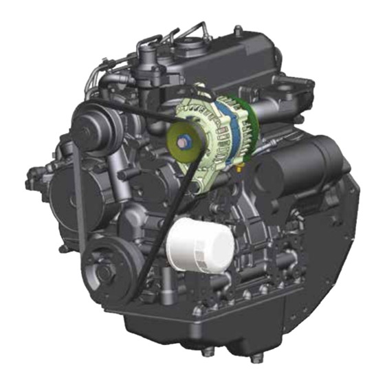
Page 4: Names Of Parts
Small Engine 1.3. NAMES OF PARTS These diagrams are to show external parts, filter and for maintenance. Some of the parts may be different depending on engines. Exhaust side Intake side (for Natural Aspirated E/G) (for Natural Aspirated E/G) 1. Exhaust manifold 1. - Page 5 RGO 60 Exhaust side Intake side (for turbo charger) (for turbo charger) 1. Turbo charger Intake manifold 2. Exhaust manifold 2. Intake hose 3. Turbo lubricant pipe (IN) 3. Oil inlet 4. Generator 4. Coolant pump 5. Oil filter 5. Cooling fan 6.
- Page 6 Small Engine 2. MAIN FUNCTIONALITY CHECKS AND REGULAR INSPECTIONS 2.1. REGULAR INSPECTION LIST Regular inspections are very important to main the best engine condition. Please adhere to the inspection list shown below for inspection details and periods. every every every 1000 hrs.
- Page 7 MEMO...
- Page 8 Small Engine 2.2. MAIN FUNCTIONALITY CHECKS ● Main functionality checks are the best for the performance and longevity of the engine. Please pay attention to the followings for the engine maintenance. 2.2.1. Visual inspections while in use ● Visual inspections around the engine: Check for oil or water leaks of fuel, lubricant and coolant. Please check each hoses and V-belt.
- Page 9 RGO 60 2.2.3. FUEL ● The property of fuel for diesel engine (cetane number, specific gravity, viscosity and etc.) influences the engine starting, output power, fuel consumption, fuel system performance, knocking or exhaustion gas. Please use 45 or higher cetane number. Be sure to use lower viscosity fuel in low temperature. ●...
- Page 10 Small Engine 2.2.4. COOLANT ● Use soft water such as tap water for the coolant. Hard water such as well water may leave deposits in the cooling system which may cause the piston scorching due to decreased cooling effect and hot coolant temperature.
-
Page 11: Air Cleaner
RGO 60 2.2.6. AIR CLEANER ● Contaminated air cleaner may not only reduce the engine output, but also increase the fuel consumption or produce black exhaust gas. ● Change air cleaner if there is any deformation, damage or cracks. ● If it is used in excessively dusty area, clean the dust collector every day, and inspect and clean the element every 50 hours or more often. - Page 12 Small Engine 2.2.11. INSPECTIONS EVERY 500 HOURS (1) Engine fuel filter change: Change the fuel filter every 500 hours after the initial change in 50 hours (2) Coolant anti-freeze change (3) Element of the air cleaner change 2.2.12. INSPECTIONS EVERY 1000 HOURS (1) TURBO CHARGER BLOWER WASHING ●...
- Page 13 MEMO...
-
Page 14: Trouble Shooting And Solution
Small Engine 3. TROUBLE SHOOTING AND SOLUTION Trouble Cause Solution 1) Charge or change if discharged. 2) Slowly heat if insufficiency caused 1) insufficient battery capacity by cold weather, recharge or change 2) Cut in a wire harness, or bad connection in battery and switch Modify terminals... - Page 15 RGO 60 Trouble Cause Solution 1) No fuel in the fuel tank. Add fuel. 2) Air present in fuel system. Remove air. 3) Fuel element blocked Wash or change 4) Air mixture at the injection pump Remove air Inspect whether there is pow- er with the Key switch on ON 5) No electricity at the fuel blocking so- position.
- Page 16 Small Engine Trouble Cause Solution 9) Blocked fuel pipe system Modify 10) Air mixed in fuel Remove air 11) Water mixed in fuel Fuel change Place in a warm garage until it 3. Insufficient engine 12) Frozen or hard wax in fuel line is thawed or soft and remove air power Replace with new fuel...
- Page 17 RGO 60 Trouble Cause Solution 1) Worn crank shaft and thrust bearing Change thrust bearing 2) Excessive timing gear back lash Change timing gear 3) Excessive valve clearance Adjust valve clearance 5. Engine noise 4) others 4) Wear in valve parts Modify or change 5) Bad coolant pump bearing Change coolant pump...
- Page 18 Small Engine Trouble Cause Solution 1) Improper oil quality Change to specified oil 2) Bad pressure control valve Change 8. Decrease in lubricant 3) Worn oil pump Change pressure 4) Bad oil pipe Modify or change 5) Worn crank metal & crank pin metal Change metal 1) Incorrect injection timing Adjust...
- Page 19 MEMO...
-
Page 20: Engine Maintenance
Small Engine 4. ENGINE MAINTENANCE 4.1. ENGINE INSPECTION 4.1.1 Cylinder compression pressure inspection ① Warm up the engine enough then stop the engine. ② Disassemble the air cleaner, muffler and injection nozzle. ③ Pull the engine stop lever to block the fuel supply. - Page 21 RGO 60 4.1.3 Top Clearance measurement ① Remove the cylinder head. But do not remove the cylinder head gasket. ② Turn the crank shaft so that piston will be at the top inside the cylinder. ③ Assemble the cylinder head. Comply with required torque when assembling the head bolt.
- Page 22 Small Engine 4.2. Engine disassembly General caution ● Please select a clean place without dust or foreign objects. ● Pay attention not to have the disassembled parts contaminated or damaged. Prepare a storage container for parts. ● Prepare cleaning agent and pressurized air for washing parts in advance. ●...
- Page 23 RGO 60 4.2.3. Turbo charger ① Disassemble the intake hose. ② Disassemble the turbo charger lubricant supply pipe and discharge pipe. ③ Disassemble the turbo charger. ※CAUTION a. Make sure there is no oil leak within the turbo. b. Turn the fan with your hand to check for damaged bearing or fan interference.
- Page 24 Small Engine 4.2.7. Fuel injection pump & speed control panel ① Remove the fuel injection pump fastening bolt & nut. ② Remove the fuel injection pump. ③ Remove the speed control panel. ※ CAUTION a. Be careful not to damage the starter spring and speed control spring while removing the fuel injection pump and speed control panel.
- Page 25 RGO 60 4.2.11. Cylinder head ① Disassemble the cylinder head bolt in descending order from 14 to 1. ② Remove the cylinder head. ※ CAUTION a. Be careful not to damage the bottom and block sides while disassembling the cylinder head.
- Page 26 Small Engine 4.2.14. V-pulley ① Remove the V-pulley bolt on the crank shaft. ② Remove the V-pulley. ③ Remove the parallel pin mounted on the crank shaft. ※ CAUTION a. Use the dedicated zig to remove the V-pulley. Do not stand in front of the pulley since it might pop out.
- Page 27 RGO 60 4.2.17. Idle gear ① Disassemble the snap ring using the snap ring puller. ② Remove the idle gear collar. ③ Remove the idle gear. ※ CAUTION a. While assembling the gear, check the steering angle of cam shaft gear, crank shaft gear and fuel cam shaft gear.
- Page 28 Small Engine 4.2.22. Connecting rod and piston ① Remove the connecting rod cap. ② Tap with a rubber mallet to remove the piston and connection rod. ※ CAUTION a. Ba careful to align the mark and number on the connecting rod when reassembling.(Figure 4.2.22_5) b.
- Page 29 RGO 60 4.2.23. Piston and piston ring ① Remove the piston pin snap ring and piston pin. ② Disassemble in order after removing the piston. ※ CAUTION a. Assemble the piston ring in the order of the Oil Ring, Second Ring and Top. b.
- Page 30 Small Engine 4.2.24. Fly wheel ① Disassemble the fly wheel bolt. ② Remove the fly wheel. ※ CAUTION a. While assembling the fly wheel, fly pin hole should be aligned with crank shaft pin. Pin hole Parallel pin 4.2.25. Main bearing case cover ①...
- Page 31 RGO 60 4.2.27. Main bearing case ① Remove the bearing case bolt 1. ② Separate the bearing case top and bottom to remove. ※ CAUTION a. There are A, B and C types of bearing cases. Be careful not to mix them up. b.
- Page 32 MEMO...
-
Page 33: Cylinder Head
RGO 60 4.3. MAJOR PARTS INSPECTION AND MAINTENANCE 4.3.1. CYLINDER HEAD 1) Cylinder head (1) Before washing the cylinder head, check for any leaks, damage or crack. ● Check the cracks on the combustion side of the head using the color check. (2) Inspect with hydrostatic test or magnetic particle testing for any invisible cracks. -
Page 34: Cylinder Block
Small Engine (5) Valve seat ● Measure the valve difference. If the indentation if more than the allowance, change the valve. Standard Allowance 0.05~0.15 mm 0.40 mm ● Valve seat modification -> When modifying the valve seat, change the valve guide if necessary. ->... - Page 35 RGO 60 (2) Cylinder inner circumference measurement ● Measure the cylinder inner circumference and change if it is more than the allowance. (mm) Allowance Category Standard cylinder inner 88.20 circumference 78.015 ~ 78.025 Cylinder 0.0 ~ 0.01 0.03 roundness Cylindericity 0.015 0.03 ●...
- Page 36 Small Engine 4.3.4. Piston and piston ring 1) 1) Piston inspection (1) Piston outer circumference ● Measure each major parts and change if any of them are more than the allowance. ● Change if there is any damage or scar on the outer surface.
- Page 37 RGO 60 (4) Connecting rod ● Measure the twist and parallel of the large and small section and change if they are more than twist the allowances. parallel Allowance Category Standard twist 100 mm 0.05 mm parallel 0.03 mm ● Connecting rod large section inspection (mm) Category Standard...
- Page 38 Small Engine 4.3.5. Crank shaft 1) Crank shaft inspection (1) Crank shaft journal inspection ● Change if there is crack or damage. ● Measure each major parts and change main bearing if it is more than the allowance. Change the crank shaft if necessary. (mm) Category Standard...
- Page 39 RGO 60 4.3.6. Cam shaft 1) Cam shaft inspection Dial gauge (1) Cam shaft exterior inspection ● Check for wear between the tappet and cam or for damage to cam gear. (2) Can shaft bend measurement ● Measure the can shaft bend. Place both ends of cam shaft journal on V block on top of a flat surface and turn the cam shaft to measure the cam journal shaking with a dial...
- Page 40 Small Engine 4.3.7. Gear 1) Gear inspection (1) Gear inspection ● Inspect the gear teeth and change if there is damage or excessive wear. (2) Gear back lash Item Standard Note Crank gear ~ idle gear 0.032~0.115 i d l e gear ~ i n jecti o n pump gear 0.032~0.115 Back idle gear ~ cam gear 0.032~0.115...
- Page 41 MEMO...
-
Page 42: Engine Operation
Small Engine 4.4. ENGINE OPERATION 4.4.1. Preparation before the operation 1) Add new engine oil in the oil tank. 2) Connect the cooling hose and add coolant. 3) Connect the fuel hose to the fuel tank. 4) Remove air from the fuel line. 4.4.2. - Page 43 RGO 60 5. MAJOR ENGINE PART MAINTENANCE 5.1. FUEL DEVICE ● The fuel system consists of the fuel tank, fuel supply feed pump, fuel filter, fuel injection pump, fuel연injection valve and parts to connect all these devices. (1). Fuel tank (5).
- Page 44 Small Engine 5.1.1. Fuel injection pump ● The fuel injection pump is a distributing type (VE) and mounted on the gear cover plate. It is operated by the injection pump gear. As a plunger rotates, fuel is distributed to each piston. Fuel is sent to the injection pump through the fuel filter coming from the fuel tank by the external feed pump and built-in feed pump.
- Page 45 140 kg/cm2 Standard pressure Adjusting pressure 145 ~ 155 kg/cm2 A1000, A1100(T) Upper limit 140kg/cm2 이상 CAUTION : Avoid dust while disassembling the nozzle holder. (4) If the initial injection pressure is not adjusted with a different thickness, change the assembly.
- Page 46 Small Engine Nozzle holder body Retaining nut spring seat space nozzle 3) Nozzle oil-tightness inspection (1) After injecting several times with the nozzle tester lever, wipe fuel off the injecting head and check if there is any fuel leak from the nozzle tube while increasing the pressure from 20kg/㎠ to 130kg/㎠. (2) If no good, disassemble the fuel injection valve and change the nozzle tube or the assembly.
- Page 47 RGO 60 5) Nozzle holder ● Disassembly (1) Lightly secure the retaining nut using a cushion bracket. (2) Secure the retaining nut with a box wrench and disassemble the nozzle holder body with a deep socket wrench. ● Nozzle tip inspection (1) Check if carbon is attached on the nozzle tip.
-
Page 48: Lubricating Device
Small Engine 5.2. LUBRICATING DEVICE ● Engine oil is pumped in through the oil suction pipe by the oil pump, moved through the oil filter and supplied to each lubricating parts. (1). Rocker arm (10). Relief valve (2). Oil pressure switch (11). - Page 49 RGO 60 1) Oil pump ● The oil pump is a trochoid type pump which is operated by the crank shaft gear. It is compact, has less pressure fluctuation and delivers 3.5kg/㎠ of pressure to each parts. ● Check the oil amount if the lubricant pump output pressure is low. Inspect the lubricant pump in the following ways if there is nothing wrong.
- Page 50 Small Engine 2) Oil pressure switch ● Connect a tester between the terminal and body to check the electricity. It is normal if there is electricity. If not, change the switch. ● Lightly press in the oil hole with a thin stick. It is normal to have no electricity.
- Page 51 RGO 60 5.3. TURBO CHARGER ● The turbo charger is operated using the exhaust gas. It pressurizes the air intake to supply to the combustion chamber so that engine power is increased. (1) Actuator (5) Compressing wheel (9) snap ring (13) Thrust sleeve (2) Turbine housing (6) turbine wheel...
- Page 52 Small Engine 2) Turbo charger oil schematic (1). Lubricant moves into the turbo charger from the cylinder block through the lubricant tubing. (2). It lubricates within the turbo charger. (3). It returns to the cylinder block through the return tubing from the turbo charger. a.
-
Page 53: Cooling Process
RGO 60 5.4. COOLING PROCESS ● This engine is water cooled. The coolant absorbs the combustion heat and engine oil heat and dissipates to the outside for a normal engine operation. The cooling system supplies coolant through the coolant pump and circulates the oil cooler to absorb the oil heat through the cooling hose. - Page 54 Small Engine 1) Auxiliary tank (Coolant time extended) pressurizing valve vapor negative pressure valve When the coolant becomes hot from the engine operation, it is cooled in the radiator by the sucked in air. However, overload or long driving will increase the water temperature and vapor maxi pressure within the radiator.
- Page 55 RGO 60 3) Coolant temperature sensor inspection ● Leave the sensor in water and add heat slowly to measure the resistance. (Resistance between the terminal and body) temperature (℃) resistance (Ω) 4) Glow plug control sensor inspection ● Measure the sensor resistance. (Resistance between the terminal and body) temperature (℃) resistance (Ω) 5) Over heat warning sensor inspection...
-
Page 56: Electrical System
Small Engine 5.5. ELECTRICAL SYSTEM 5.5.1. Starter ● Circuit diagram ● Specification item detail note output 12V / 2.2kW Number of pinion teeth Electricity without 12.5V load ● Inspection 1) Pull in coil test of the magnetic switch (solenoid) The pull-in coil is normal if plunger is sucked in and pinion pops out with the battery in contact between battery the magnetic switch S-M terminals. - Page 57 RGO 60 2) Holding coil of the magnetic switch test Manually pull the pinion to the stopper location while the battery is in contact between the magnetic switch S terminal and body. The hold in winding is battery normal, if it returns when let go. connector separated starter motor CAUTION...
- Page 58 Small Engine ● Starter parts cleaning 1) Do not soak parts in solvent. When yoke, field coil assembly or commutator is soaked in solvent, their insulation will be damaged. When these parts are dirty, wipe then with cloth. 2) Do not soak the driver unit in detergent since washing in detergent will clean out the clutch oil of the over running clutch which is oiled at the manufacturer.
- Page 59 RGO 60 5) Brush holder This is to test conductivity between the brush holder and plate holder. It is normal if it is not conductive. brush holder 6) Over running clutch 1. Check if the pinion is locked when turned to left and turns smoothly when turned to right.
- Page 60 Small Engine 3) Commutator coil grounding test Growler C h e c k b e t w e e n t h e c o m m u t a t o r s e g m e n t and armature coil cores.
- Page 61 RGO 60 5.5.2. Generator (alternator) ● Basic circuit diagram ● Specification Item detail Remarks Type AC generating rectifier-type Output 12V / 50A Motor speed 1,000~18,000 rpm Regulator setting voltage 14.7 ± 0.3V Temperature compensation -7 ± 3mV/℃ ● Inspection 1) Generator output measurement while the engine is running (1) Connect the positive (+) terminal of the voltmeter to the output (B+) terminal of the generator and...
- Page 62 Small Engine 2) Lamp circuit test while the engine is on (1) Connect the positive (+) terminal of the voltmeter to the lamp line and ground the negative (-) terminal of the voltmeter. (2) If the lamp is not on or there is no output while the engine is running, then lamp line or lamp may be short.
- Page 63 RGO 60 5) Rotor 1. This is a rotor coil conductivity test to check the conductivity between the slip rings. Measure the resistance of the rotor. If the resistance is very low, that means it is shorted. If there is no conductivity or a short, replace the rotor assembly.
- Page 64 Small Engine ● Disassembled diagram and parts 1. nut 8. rotor assembly 14. separating plate 2. pulley 9. stator assembly 15, 16, 19. insulation 3, 6. spacer 10. bearing (rear) 17. brush, adjustor combination 4. moving frame 11. gap ring 18, 20, 21.
- Page 65 RGO 60 ● Regulating voltage inspection of the IC regulator (with no load) 1) Specialty wiring connector, voltmeter and ammeter are set as shown in diagram below. Load Ignition switch Altenator Yellow Ammeter Voltmeter Battery 2) Inspect in the order shown in the table below. determination order Inspection item...
-
Page 66: Electrical Wiring
Small Engine 5.5.3. ELECTRICAL WIRING 5.5.3.1. Electrical wiring diagram ● The following electrical wiring is a representative example. KUKJE RGO 60... - Page 67 RGO 60 5.4.3.2. Electrical wiring connector Fuel cut wiring Korea Union Machine Fuel stopping solenoid Starter wiring Controller wiring Engine control unit starter Generator wiring generator KUKJE RGO 60...
- Page 68 Small Engine 5.5.3.3. Electrical wiring 1) Generator (alternator) ● Do not connect the battery in opposite terminals. If plus and minus terminals of battery cable are connected in reverse, generator diode may be damaged and the battery will not be charged. The stator coil will also be damaged. To prevent the reverse connection, adjust the battery cable length or there should be solution to prevent it from the manufacturer.
- Page 69 MEMO...
- Page 70 Small Engine 6. MAINTENANCE STANDARD TABLE 6.1. MAIN PARTS TIGHTENING TORQUE Width of hexagonal Clamping torque Item Size Remarks side(mm) (kgf・m) M10× Cylinder head bolt 6.75±0.25 1.25 Connecting rod bolt M8×1.0 4.5±0.2 M10× Fly wheel mounting bolt 6.75±0.25 1.25 Metal cap mounting bolt M8×1.25 3.25±0.25 Crank shaft V-pulley...
- Page 71 RGO 60 6.3. ENGINE ASSEMBLY TOLERANCE 6.3.1. Cylinder head Model A1000, A1100, A1100T Remarks Item standard allowance Cylinder head combustion surface bent 0.03 or less 0.15 Intake 120° Belt seat angle Exhaust 90° Intake 1.6±0.1 2.23 Belt seat width Exhaust 1.6±0.1...
- Page 72 Cylinder block inner cir- 0 ~ 0.015 0 ~ 0.015 cumference roundness 6.3.3 Valve rocker arm Model A1000, A1100, A1100T Note Item Standard Allowance Rocker arm shaft φ13 -0.020 outer circumfer- φ12.95 Intake and exhaust rocker arm -0.045...
- Page 73 RGO 60 6.3.5 Piston ring Model A1000, A1100, A1100T note Item standard allowance Ring groove width 1.896±0.01 1.803 0 Ring width -0.024 Top ring Gap between ring 0.15 ~ 0.30 and ring groove End gap 0.15 ~ 0.30 1.5 +0.09 Ring groove width +0.07...
- Page 74 Small Engine 6.3.7 Cam axis Model A1000, A1100, A1100T note Item standard allowance Cam shaft journal φ36 -0.050 outer circumfer- φ35.89 -0.066 Gear side ence Oil clearance 0.050 ~ 0.091 Cam shaft journal φ36 -0.050 outer circumfer- φ35.89 middle -0.066...
-
Page 75: Special Tools
RGO 60 6.4 SPECIAL TOOLS Tool specification (unit: mm) diagram Tool Stem seal pressurizing zig Flywheel oil seal pressurizing zig Gear case oil seal pressurizing Plate-type plug pressurizing Governor axis gear pressurizing KUKJE RGO 60... - Page 76 Small Engine Tool specification (unit: mm) diagram ToolTool Available in regular retail market Piston assembling zig (applicable to φ60 ~ φ125) Piston ring assembling zig Available in regular retail market Oil filter wrench Available in regular retail market KUKJE RGO 60...
- Page 77 MEMO...
Need help?
Do you have a question about the A1000 and is the answer not in the manual?
Questions and answers