
Summary of Contents for Baker Becker VRP-CH Series
- Page 1 VRP-CH Series Valve Regulator Pilots Instruction Manual (Rev.A) Baker Hughes Data Classification : Public...
- Page 2 OPERATOR ARE STRICTLY LIMITED TO THOSE EXPRESSLY PROVIDED IN THE CONTRACT RELATING TO THE SUPPLY OF THE EQUIPMENT. NO ADDITIONAL REPRESENTATIONS OR WARRANTIES BY BAKER HUGHES REGARDING THE EQUIPMENT OR ITS USE ARE GIVEN OR IMPLIED BY THE ISSUE OF THESE INSTRUCTIONS.
-
Page 3: Table Of Contents
Copyright 2023 Baker Hughes Company. All rights reserved. Becker VRP-CH Series Valve Regulator Pilot Instruction Manual | 3... -
Page 4: Scope Of Manual
Becker pilots. If there are less to help ensure adequate operating speed. The bleed to any questions concerning these instructions, contact your Baker pressure system eliminates atmospheric emissions by keeping Hughes sales representative or sales office before proceeding. -
Page 5: Technical Information
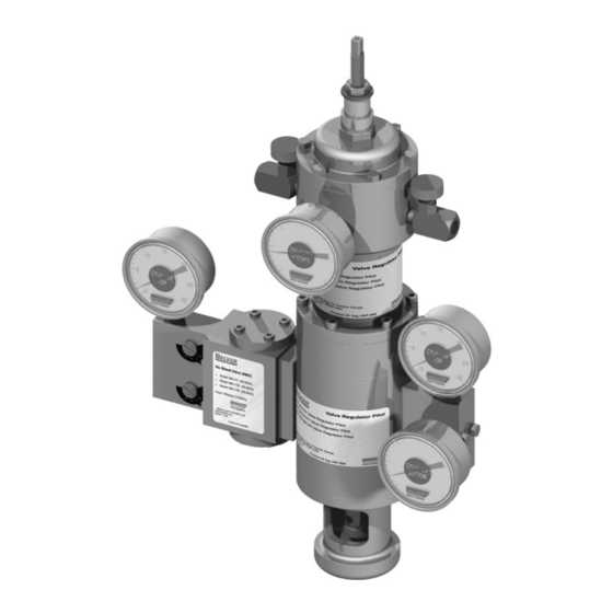
Baker Hughes • 2-inch pipe mount provided for retrofit to other manufacturers’ actuators VRP-1000-CH VRP-1500-CH VRP-175-CH VRP-600-CH VRP-CH pilots - model numbers Copyright 2023 Baker Hughes Company. All rights reserved. Becker VRP-CH Series Valve Regulator Pilot Instruction Manual | 5... -
Page 6: Vrp-Ch Pilot Selection Chart
6550 kPa 6550 kPa These models should only be used for applications that require high gain. Consult Baker Hughes prior to selecting these models. Remote Setpoint Change Options • The SM-1000 series motors accept a 24 VDC or 120 VAC input. The SM-1100 series motors accept a 4-20 MA signal and require a separate 24 VDC or 120 VAC power connection. -
Page 7: Principles Of Operation
• If equipped with a PS sensor and/or VB-250, volume boosters, or any other disassembly or reassembly of the pilot. see page 17. Copyright 2023 Baker Hughes Company. All rights reserved. Becker VRP-CH Series Valve Regulator Pilot Instruction Manual | 7... - Page 8 “False Signal” cylinder bottom equalize at a pressure equivalent to the pressure. proper cylinder balance pressure (P WARNING: DO NOT turn the sensitivity adjustment 13. Verify “False Signal”: 8 | Baker Hughes Copyright 2023 Baker Hughes Company. All rights reserved.
-
Page 9: Fine Tuning Procedures
While certain VRP models will become insensitive on even minimal rotation, turning more than one full turn will guarantee excessive deadband on any VRP model. Copyright 2023 Baker Hughes Company. All rights reserved. Becker VRP-CH Series Valve Regulator Pilot Instruction Manual | 9... -
Page 10: Inspection Procedure
VRP-CH is equipped with the NBV sensor, the “EX” port pressure must be increased. should be bubble tight. The gauge output should reverse Note: Check with Baker Hughes before increasing originally when the pressure is dropped. Failure to build output specified power gas to prevent equipment failure due to pressure to full supply pressure is a sign of a worn pilot overpressure. -
Page 11: Annual Maintenance Checklist
Simply contact Baker Hughes and refer to the following part number: VRP-CH Pilot Model Repair Kit Part No. VRP-175-CH 30-9002 VRP-600-CH 30-9004 VRP-1000/1500-CH 30-9005 Copyright 2023 Baker Hughes Company. All rights reserved. Becker VRP-CH Series Valve Regulator Pilot Instruction Manual | 11... -
Page 12: Vrp-Ch Pilot Blank Parts
VRP-CH Pilot Blank Parts 12 | Baker Hughes Copyright 2023 Baker Hughes Company. All rights reserved. -
Page 13: Vrp-Ch Pilot Spring Chambers Parts
1/4-20 x 2” SCHS (SS) for 600-CH Stainless steel versions available Item #10 is 98-2614 (8-32 x ½” SS) for VRP models 175/600-CH Spring Chamber Copyright 2023 Baker Hughes Company. All rights reserved. Becker VRP-CH Series Valve Regulator Pilot Instruction Manual | 13... - Page 14 Inner Tube 98-3231 1/4-20 x 2” SCHS (SS) Stainless steel versions available Item #10 is 98-2614 (8-32 x ½” SS) for VRP models (except 1500-CH) 1000/1500-CH Spring Chamber 14 | Baker Hughes Copyright 2023 Baker Hughes Company. All rights reserved.
-
Page 15: Vrp-Ch Pilot Sensing Chambers Parts
30-7011 Conv. Diaphragm w/Hole 95-2615 O-ring - 012 30-7058 Top Spacer 1000/1500-CH Sensing Chamber Maximum allowable operating pressure (MAOP) = 1500 psig Copyright 2023 Baker Hughes Company. All rights reserved. Becker VRP-CH Series Valve Regulator Pilot Instruction Manual | 15... -
Page 16: Appendix
5 percent or operation. a) Pilot bleeds to the atmosphere: S x D = 0.148 x T + 460 16 | Baker Hughes Copyright 2023 Baker Hughes Company. All rights reserved. -
Page 17: Accessories
(decreasing numbers) and then turn it back to based upon power gas pressure and the left (increasing numbers) by small increments until stability discharge gas pressure. is achieved. Copyright 2023 Baker Hughes Company. All rights reserved. Becker VRP-CH Series Valve Regulator Pilot Instruction Manual | 17... -
Page 18: Assembly Procedures
(F2). Press fit the seat (E) into the valve adjust- ing screw (F2). Then install the assembly into the inside piston (I) and connect it to the posts (G) with 8-32 x 1-inch SHCS (H2). 18 | Baker Hughes Copyright 2023 Baker Hughes Company. All rights reserved. - Page 19 Step 9. Place O-ring -010 (A) in the nuts (M2) and secure the adjusting orifice (K2) with nuts (M2) in the orifice manifold (M1) as shown. Copyright 2023 Baker Hughes Company. All rights reserved. Becker VRP-CH Series Valve Regulator Pilot Instruction Manual | 19...
- Page 20 Step 13. Bolt the gauge manifold (C2) and orifice manifold (M1) to the body (C) with two 1/4 - 20 x 2 1/2-inch HHCS (AA) each as shown . 20 | Baker Hughes Copyright 2023 Baker Hughes Company. All rights reserved.
-
Page 21: 175-Ch Chamber Assemblies
(H). Attach the thread extension (E) to the inner tube (I) using 1/2-20 SS jam nut (J). Torque the jam nut (J) to 100-110 in.-lbs. Copyright 2023 Baker Hughes Company. All rights reserved. Becker VRP-CH Series Valve Regulator Pilot Instruction Manual | 21... - Page 22 Jam Nut (J) in the cartridge assembly step. When Inner Tube (I) cannot be rotated any more do not force it, this assembly should only be hand-tight. 22 | Baker Hughes Copyright 2023 Baker Hughes Company. All rights reserved.
- Page 23 (6) Fiberglass Washers (P) and six (6), 1/4-20 x 7/8” SHCS (Q). Bolt Bottom Flange (K) into Cartridge Spacer (G) using eight (8), 1/4-20 x 1 1/2” HHCS (R). Copyright 2023 Baker Hughes Company. All rights reserved. Becker VRP-CH Series Valve Regulator Pilot Instruction Manual | 23...
- Page 24 600-CH Spring Chamber Assembly Bolt the spring chamber (D) to the top body assembly (H) using six (6) fiberglass washers (J) and six (6) 1/4-20 x 2-inch SHCS (K). 24 | Baker Hughes Copyright 2023 Baker Hughes Company. All rights reserved.
-
Page 25: 1000/1500-Ch Chamber Assemblies
(H). Attach the thread extension (E) to the inner tube (I) using 1/2-20 SS jam nut (J). Torque the jam nut (J) to 180-220 in.-lbs. Copyright 2023 Baker Hughes Company. All rights reserved. Becker VRP-CH Series Valve Regulator Pilot Instruction Manual | 25... -
Page 26: Bearing Case Assembly
(G). Thread 1/2-20 SS left-hand jam nut (F) onto the screw (E). The jam nut (F) and bearing nut (G) should be tightened against each other as shown in Figure 15. 26 | Baker Hughes Copyright 2023 Baker Hughes Company. All rights reserved. -
Page 27: Control Spring Assembly
(E), then replace the spring (J) and repeat the test. If the spring (J) is satisfactory then move to tube cap assembly. Copyright 2023 Baker Hughes Company. All rights reserved. Becker VRP-CH Series Valve Regulator Pilot Instruction Manual | 27... -
Page 28: 175/600-Ch Cap Assembly
(F) pressure ports. Bolt the cap (B) to the spring chamber (G) using six (6) 1/4-20 x 3/4-inch HHCS (H). 28 | Baker Hughes Copyright 2023 Baker Hughes Company. All rights reserved. -
Page 29: 1000/1500 Ch Cap Assembly
(F) pressure ports. Bolt the cap assembly (B) to the spring chamber (G) using twelve (12), 1/4-20 x 3/4-inch HHCS (H). Copyright 2023 Baker Hughes Company. All rights reserved. Becker VRP-CH Series Valve Regulator Pilot Instruction Manual | 29... -
Page 30: Part Silhouettes
Part Silhouettes 30 | Baker Hughes Copyright 2023 Baker Hughes Company. All rights reserved. - Page 31 Part Silhouettes Copyright 2023 Baker Hughes Company. All rights reserved. Becker VRP-CH Series Valve Regulator Pilot Instruction Manual | 31...
- Page 32 Part Silhouettes 30-7011 SMALL DIAPHRAGM FOR: 1000/1300-CH SENSING ASSEMBLY 32 | Baker Hughes Copyright 2023 Baker Hughes Company. All rights reserved.
- Page 33 Notes: Copyright 2023 Baker Hughes Company. All rights reserved. Becker VRP-CH Series Valve Regulator Pilot Instruction Manual | 33...
- Page 34 Notes: 34 | Baker Hughes Copyright 2023 Baker Hughes Company. All rights reserved.
- Page 35 Notes: Copyright 2023 Baker Hughes Company. All rights reserved. Becker VRP-CH Series Valve Regulator Pilot Instruction Manual | 35...
- Page 36 Copyright 2023 Baker Hughes Company. All rights reserved. Baker Hughes provides this information on an “as is” basis for general information purposes. Baker Hughes does not make any representation as to the ac- curacy or completeness of the information and makes no warranties of any kind, specific, implied or oral, to the fullest extent permissible by law, including those of merchantability and fitness for a particular purpose or use.
Need help?
Do you have a question about the Becker VRP-CH Series and is the answer not in the manual?
Questions and answers