Table of Contents
Advertisement
Quick Links
Advertisement
Table of Contents

Summary of Contents for Neumo RIEGER N1
- Page 1 Operating and maintenance manual HYGIENIC-MIX PROOF VALVES N1 / NV1 Translation...
- Page 2 HYGIENIC-MIX PROOF VALVES N1 / NV1 General Gebr. Rieger GmbH + Co. KG Kochertalstraße 32 73431 Aalen; Germany Telephone: + 49 (0) 73 61 / 57 02-0 Telefax: + 49 (0) 73 61 / 57 02-51 http//www.rr-rieger.de E-Mail: info@rr-rieger.de © Gebr. Rieger GmbH + Co. KG | D-73431 Aalen All rights reserved in particular the right of duplication and distribution as well as translation No part of the manual may be reproduced in any form or electronically stored, processed, duplicated or distributed without the written permission of Gebr.
-
Page 3: Table Of Contents
HYGIENIC-MIX PROOF VALVES N1 / NV1 General Table of content General ............................7 Changes and reservations ....................... 7 Warranty and liability ......................7 Scope of delivery ........................8 Documentation ........................8 Signs and symbols in this manual .................... 8 1.5.1 Safety signs ........................ - Page 4 HYGIENIC-MIX PROOF VALVES N1 / NV1 General 4.2.5 Casing ..........................17 4.2.6 Nominal diameter ......................18 4.2.7 Seal ..........................19 4.2.8 Material of the casing ....................20 4.2.9 Function of the leakage space ..................20 4.2.10 Actuator ......................... 20 Special configurations ......................22 4.3.1 Suitable for potentially explosive areas acc.
- Page 5 HYGIENIC-MIX PROOF VALVES N1 / NV1 General Safety during operation ......................32 During operation ........................32 Shutdown of the valve ......................32 Maintenance..........................33 Safety during maintenance and repair of the valve .............. 33 General ..........................33 Cleaning ..........................34 9.3.1 Cleaning .........................
- Page 6 HYGIENIC-MIX PROOF VALVES N1 / NV1 General 10.3 Faults, possible causes and their remedy................50 Disposal ............................. 52 Documentation of the Suppliers ....................53 12.1 Connection and function of the control head ............... 53 Page 6 of 54 2021 BA-N1_NV1_EN-GB_Rev05...
-
Page 7: General
HYGIENIC-MIX PROOF VALVES N1 / NV1 General 1 General These operating and maintenance instructions contain important information to assist you in the safe, economic and proper use of the valve. The operating and maintenance instructions are also directed to qualified, instructed and trained personnel who are responsible for installing the valve to an existing system or disassembling it. -
Page 8: Scope Of Delivery
HYGIENIC-MIX PROOF VALVES N1 / NV1 General 1.3 Scope of delivery The scope of delivery results from the order and the shipping documentation. 1.4 Documentation The operating and maintenance instructions are an integral part of the product and thus part of the scope of delivery. One copy of these instructions shall be made available to the authorised personnel for the entire service life of the valve and be complete and legible. -
Page 9: Name Plate
HYGIENIC-MIX PROOF VALVES N1 / NV1 General Information INFORMATION Helpful information for safe operation of the system is given here. 1.6 Name plate Every valve has a type plate that enables clear identification and includes the most important technical data. Gebr. -
Page 10: Personal Protective Equipment
HYGIENIC-MIX PROOF VALVES N1 / NV1 General be at least 18 years old. be familiar with and able to apply the accident prevention regulations and safety instructions for the system. have been trained and instructed on the rules of conduct in the event of a malfunction. ... -
Page 11: Used Abbreviations And Technical Terms
HYGIENIC-MIX PROOF VALVES N1 / NV1 General the authorised personnel have understood the documentation and can implement it in practice. only authorised personnel perform maintenance work and fault rectification the operating instructions are always available at the valve operation point, in a legible and complete condition. -
Page 12: Packaging, Transport And Storage
HYGIENIC-MIX PROOF VALVES N1 / NV1 Packaging, transport and storage 2 Packaging, transport and storage 2.1 Packaging To ensure sufficient protection during transport the valve was packed carefully. When the product is received, the packaging and the product should be checked for any damage. A damaged valve must not be put into operation. -
Page 13: Safety
HYGIENIC-MIX PROOF VALVES N1 / NV1 Safety 3 Safety Read the following safety instructions and information on safe operation before starting work. Familiarise yourself with all functions. Store these instructions in a safe place and pass them on as necessary. In addition to the safety instructions in these instructions, the relevant statutory and internal regulations, rules and guidelines must also be observed at the installation site. -
Page 14: Residual Hazards
HYGIENIC-MIX PROOF VALVES N1 / NV1 Safety Misuse includes: Use in explosive atmosphere. Operation of the valve with other data than the agreed technical data. Operation of the valve in a not authorized installation position. Operation of the valve for applications for which a certificate is required, unless the valve was ordered for this application and this is confirmed in the order;... -
Page 15: Noise
HYGIENIC-MIX PROOF VALVES N1 / NV1 Safety Danger due to unprotected valve mechanisms Unprotected valve mechanisms can pose shearing, crushing and pinching hazards during installation, commissioning and setting work. No second person is permitted in the danger zone during these activities. ... -
Page 16: Description
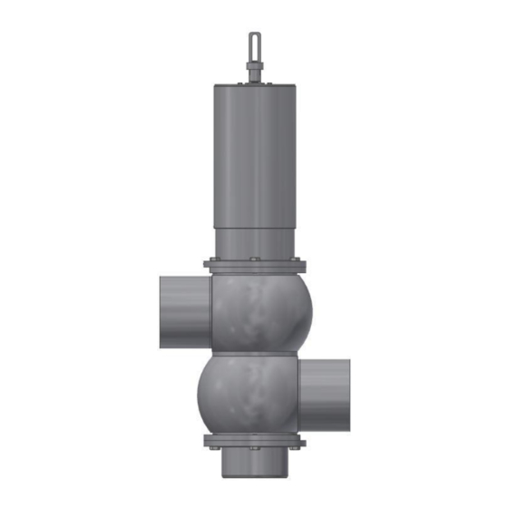
HYGIENIC-MIX PROOF VALVES N1 / NV1 Description 4 Description RIEGER mix proof valves N1 are used for the mix-proof isolation of two lines of the system's pipeline system. In this manual N1 is used also for NV1 valves. They are developed, designed and built for commercial and industrial use. The leakage drain is placed, so that this valve is suitable for vertical installation. -
Page 17: Valve Type
HYGIENIC-MIX PROOF VALVES N1 / NV1 Description 301 10 .0 00 .01 .0404 .32 Valve type Clocking Parts of the casing Outlets Special versions Material of the seal nominal diameter Material of the casing Figure 2 Example item number 4.2.3 Valve type The combination „N1“... -
Page 18: Nominal Diameter
HYGIENIC-MIX PROOF VALVES N1 / NV1 Description Number Meaning Casing one part = without clamp Casing two parts = without clamp Casing three parts = without clamp Table 5 Definition of the casings in the item number Arrangement of the outlets Type designation: N1.XX.XXX-XX Item number: 301XX.XXXX.XX.XXXX.XX N1.01... -
Page 19: Seal
HYGIENIC-MIX PROOF VALVES N1 / NV1 Description Nominal diameter N1.XX.XXX-XX: In the type designations a two-digit number combination indicates, which size the nominal diameters are. If the upper and lower nominal diameters differ, both nominal diameters are written, separated by a slash „/“. 301XX.XXXX.XX.XXXX.XX: In the item number a four-digit number combination indicates, which size the nominal diameters are. -
Page 20: Material Of The Casing
HYGIENIC-MIX PROOF VALVES N1 / NV1 Description 4.2.8 Material of the casing Depending on the medium and the application the material of the casing is chosen. In the article number this is defined by the last two numbers. The most used materials are: ... - Page 21 HYGIENIC-MIX PROOF VALVES N1 / NV1 Description Figure 4 Air connections at the actuator Air connection L1 In case of a closed valve the air supply at L1 is closed. Due to the pressure of the pressure spring in the actuator the valve closes with the valve disc in the casing seat. If the air supply is pressurised, the valve opens and releases the pipe cross section.
-
Page 22: Special Configurations
HYGIENIC-MIX PROOF VALVES N1 / NV1 Description Figure 6 Air connection L2 pressurised with air The cleaning medium drains via the pipeline and the lower valve disc. If L2 is depressurised, valve disc 1 moves back into its initial position. Air connection L3 If the air supply L3 is applied with air, the valve disc by the upper pipeline clocks to the upper pipeline. -
Page 23: 3-A Certification
HYGIENIC-MIX PROOF VALVES N1 / NV1 Description 4.3.2 3-A certification Valves with a 3-A certification are according to the American 3-A standard number 85-03 (. In the order it has to be stated that the valve must fulfil the 3-A standard. Then the valve is according to the requirements, the certificates are made and delivered with the order. -
Page 24: Technical Data
HYGIENIC-MIX PROOF VALVES N1 / NV1 Technical data 5 Technical data The application range of the valve as well as the materials that come into contact with the product must always be adapted to the corresponding operating conditions. This shall be defined by the owner and coordinated with the manufacturer. -
Page 25: Operating Data
HYGIENIC-MIX PROOF VALVES N1 / NV1 Technical data Tube 70 x 2 85 x 2 104 x 2 129 x 2 154 x 2 204 x 2 On demand Inch Tube 1” 25.4 x 1.65 On demand 1 ½ ” 38.1 x 1.65 2 ”... -
Page 26: Permissible Product Temperatures
HYGIENIC-MIX PROOF VALVES N1 / NV1 Technical data 5.3.4 Permissible product temperatures The permissible product temperatures depend on the material of the seals. For special materials, the data sheet in the Appendix must be observed. Material Time Temperature in °C Temperature in °F EPDM, FKM continuous... -
Page 27: Assembly / Installation
HYGIENIC-MIX PROOF VALVES N1 / NV1 Assembly / Installation 6 Assembly / Installation 6.1 Connection WARNING Risk of injury due to incorrect connection! Hoses and pipes not or incorrectly connected can result in malfunctions. That could put the safety of the operating personnel at risk. All connections, hoses and pipes must be routed in such a way that there are no tripping hazards. -
Page 28: Installing The Valve In A Pipeline
HYGIENIC-MIX PROOF VALVES N1 / NV1 Assembly / Installation 6.3 Installing the valve in a pipeline When planning the installation situation for the valve, it must be taken into account that the working area is freely accessible to the operator. We recommend a space of 1 m to the right and left of the valve and on the operator side. -
Page 29: Installing The Valve Parts
HYGIENIC-MIX PROOF VALVES N1 / NV1 Assembly / Installation Tack at four points, offset by 90°. In case of nominal diameters ≥ 50mm tack at four further points, offset by 45° to the first tack points. Weld the casing welding end to the piping. Therefore, use WIG welding procedure with pulses (manually or with automatic orbital welding). - Page 30 HYGIENIC-MIX PROOF VALVES N1 / NV1 Assembly / Installation CAUTION Risk of injuries due to too big distances of the sensors! If the sensors are installed too far away from the spindle, it is possible to grasp between sensor and spindle and injuries may be caused. Install the sensor at maximum 2 mm away from the spindle.
-
Page 31: Commissioning
HYGIENIC-MIX PROOF VALVES N1 / NV1 Commissioning 7 Commissioning 7.1 Safety during commissioning Check the valve visually prior to initial commissioning. A damaged valve must not be put into operation. Commissioning may only be carried out by qualified persons, taking the safety instructions into account. -
Page 32: Operation
HYGIENIC-MIX PROOF VALVES N1 / NV1 Operation 8 Operation 8.1 Safety during operation WARNING Danger due to incorrect operation! Operating the valve incorrectly or in an incorrect state poses a hazard risk. Therefore, observe the operating and maintenance instructions for the entire system. Only operate the system if all protective devices are present and fitted. -
Page 33: Maintenance
HYGIENIC-MIX PROOF VALVES N1 / NV1 Maintenance 9 Maintenance The chapter on maintenance is intended exclusively for qualified personnel. Maintenance, cleaning and repair work may only be carried out by qualified personnel. The manufacturer accepts no liability for damage resulting from incorrectly performed maintenance, cleaning and repair work or from the actions of unauthorised persons or third parties. -
Page 34: Cleaning
HYGIENIC-MIX PROOF VALVES N1 / NV1 Maintenance 9.3 Cleaning WARNING Danger due to cleaning agents! Cleaning agents are chemical products that may have a harmful effect on health, e.g. if they get into the skin or eyes. Do not fail to observe the cleaning agent manufacturer's safety data sheets. Wear protective gloves and safety glasses according to the safety data sheet. -
Page 35: Cleaning And Sterilisation In Process
HYGIENIC-MIX PROOF VALVES N1 / NV1 Maintenance Flush the interior of the valve on a regular basis with a suitable medium, e.g. during product changes, downtimes or other production breaks. These intervals must be defined by the system owner. ... - Page 36 HYGIENIC-MIX PROOF VALVES N1 / NV1 Maintenance max. 150 °C that corresponds to 302 °F temperature; in case of HNBR seals in areas in contact with product max. 130 °C, that corresponds to 275 °F. The recommended cleaning parameters are intended as guideline values. The operator must determine the cleaning parameters actually required for the particular product.
-
Page 37: Table Of Cleaning Agents
HYGIENIC-MIX PROOF VALVES N1 / NV1 Maintenance 9.3.3 Table of cleaning agents Cleaning agent/disinfectant: Max. Chloride Concentration Maximum Max. Always observe the maximum content in exposure temperature from – to in % values preparation time in water in mg/l minutes 304* 316L** °C... -
Page 38: Maintenance Intervals
HYGIENIC-MIX PROOF VALVES N1 / NV1 Maintenance 9.4 Maintenance intervals To achieve a long service life of the valve, it must be serviced at regular intervals and on schedule. NOTICE Danger of machine damage due to worn components! Carry out the prescribed maintenance and inspection work on schedule. The following inspection and maintenance work must be carried out at regular intervals. -
Page 39: Pressure Spring Guideline Values
HYGIENIC-MIX PROOF VALVES N1 / NV1 Maintenance 9.4.2 Pressure spring guideline values We recommend changing the pressure springs in the actuators after max. 5 years of use. For multi-switching valves, we recommend replacing the springs after 2 years. NOTICE Danger due to worn pressure spring! Extremely frequent switching can significantly reduce the lifespan of the pressure spring. -
Page 40: Lubrication Plan
HYGIENIC-MIX PROOF VALVES N1 / NV1 Maintenance 9.4.4 Lubrication plan Seals and running surfaces are lubricated with grease. The specified grease types are adapted to the materials. If a grease other than the one specified is used, sealing elements may be corroded and no longer fulfil their function. Do not use mineral oils or animal product-based greases. -
Page 41: Parts Of The Valve
HYGIENIC-MIX PROOF VALVES N1 / NV1 Maintenance 9.6 Parts of the valve 9.6.1 Explosionszeichnung Valves > DN100 Figure 11 Mix proof valve N1 BA-N1_NV1_EN-GB_Rev05 2021 Page 41 of 54... -
Page 42: Designation Of The Parts
HYGIENIC-MIX PROOF VALVES N1 / NV1 Maintenance 9.6.2 Designation of the parts Designation Designation Actuator O-ring outside upper valve disc Spindle in the actuator Guide sleeve O-Ring spindle in the actuator Counter nut AF13 Guide band Cap nut O-ring guide O-ring lower valve disc Guide Lower valve disc... -
Page 43: Disassembling The Valve From The Casing
HYGIENIC-MIX PROOF VALVES N1 / NV1 Maintenance Wrench for loosening the nut at the clamp connection RIEGER O-ring Tool Kit (order number 3001591) RIEGER Assembly wrench DN25-DN100 AF13 Item No.: 5006697 Standard socket wrench AF13 9.7.3 Disassembling the valve from the casing Depressurise the pipe system and the compressed air connection of the pneumatic actuator. -
Page 44: Disassembly Of The Remaining Seals For Maintenance
HYGIENIC-MIX PROOF VALVES N1 / NV1 Maintenance Figure 13 Disassembled lower guide (6) Remove the lower guide (6). 9.7.4 Disassembly of the remaining seals for maintenance Place all parts on a clean, soft, lint-free surface. Guide the RIEGER assembly socket wrench from below into the lower valve disc (16) and unscrew the cap nut (14) from the spindle. -
Page 45: Assembly
HYGIENIC-MIX PROOF VALVES N1 / NV1 Maintenance Figure 16 Upper valve disc (9) with upper guide (6) with guide band (4) and seals(5 and 7), guide sleeve (12) Check the running and mating surfaces for damage, smooth if necessary. Lever out the seals and guide bands with the RIEGER O-Ring Tool Kit and check them for damage. -
Page 46: Assembly Of The Valve Parts
HYGIENIC-MIX PROOF VALVES N1 / NV1 Maintenance RIEGER Assembly wrench DN25-DN100 AF13 Item No.: 5006697 Standard socket wrench AF13 9.8.3 Assembly of the valve parts The sizes of the O-rings and sleeve bearings can be taken from the spare parts list. The assembly of the mix proof valve is done in reverse sequence as the disassembly. - Page 47 HYGIENIC-MIX PROOF VALVES N1 / NV1 Maintenance Figure 20 Upper valve disc (9), upper guide (6) and guide sleeve (12) assembled on the spindle (2) Assemble the O-ring (15) and assemble it on the lower valve disc (16). The O-ring is very stable and must be pressed crosswise into the groove.
-
Page 48: After Assembly
HYGIENIC-MIX PROOF VALVES N1 / NV1 Maintenance If the cylinder is mounted correctly, it will run smoothly and quietly. No hissing noise can be heard. If the cylinder is not tight or jerking, it must be sent in for maintenance. Pressurise the air hose. -
Page 49: Adjusting The Stroke At The Lower Valve Seat
HYGIENIC-MIX PROOF VALVES N1 / NV1 Maintenance Are all screw fittings fastened firmly and tight? See torque table on page 39. Are all pneumatic hose connections tight? Are the pipes and screw fittings used approved for use within the pressure range? ... -
Page 50: Troubleshooting
HYGIENIC-MIX PROOF VALVES N1 / NV1 Troubleshooting 10 Troubleshooting 10.1 What to do in an emergency? In case of emergency: stop the product supply immediately. Therefore, an emergency stop switch must be integrated into the system. 10.2 Safety during fault rectification In the event of a fault, pay attention to the local safety regulations! Make sure that no unauthorised persons are present in the area of the system. - Page 51 HYGIENIC-MIX PROOF VALVES N1 / NV1 Troubleshooting Fault Possible cause Remedy Pilot valve defective Check control button, replace pilot valve. O-ring defective Remove and dismantle valve. Check O-ring seats and replace them if necessary. Valve moving too slowly Compressed air insufficient Increase air quantity or air pressure (min.
- Page 52 HYGIENIC-MIX PROOF VALVES N1 / NV1 Disposal 11 Disposal Packaging materials, used or residual operating materials and defective parts must be recycled. Observe the applicable regional regulations as well as national regulations for this. Page 52 of 54 2021 BA-N1_NV1_EN-GB_Rev05...
- Page 53 HYGIENIC-MIX PROOF VALVES N1 / NV1 Documentation of the Suppliers 12 Documentation of the Suppliers All valves must be adjusted in assembled and connected operation condition on site by the operator or system engineer. The switching units must be adjusted, too. Declarations of conformity for the individual materials used can be requested from the manufacturer if required.
- Page 54 RIEGER worldwide own branches representatives Gebr. Rieger GmbH + Co. KG Kochertalstraße 32 73431 Aalen, Germany Telephone: + 49 (0) 73 61 / 57 02-0 Fax: + 49 (0) 73 61 / 57 02-51 http//www.rr-rieger.de E-Mail: info@rr-rieger.de...
Need help?
Do you have a question about the RIEGER N1 and is the answer not in the manual?
Questions and answers